TouchGFX on NeoChrom/NeoChromVG
This section discusses how to use TouchGFX on hardware having the NeoChrom GPU graphics accelerator. This graphics accelerator improves the performance significantly for operations like texture mapping, image scaling and rotation. This means that more advanced UIs can be built while still keeping a high frame rate.
The NeoChrom graphics accelerator is currently available in STM32U5x7, STM32U5x9, STM32H7R7/S7 and STM32N6 microcontrollers. Development boards are available for all families.
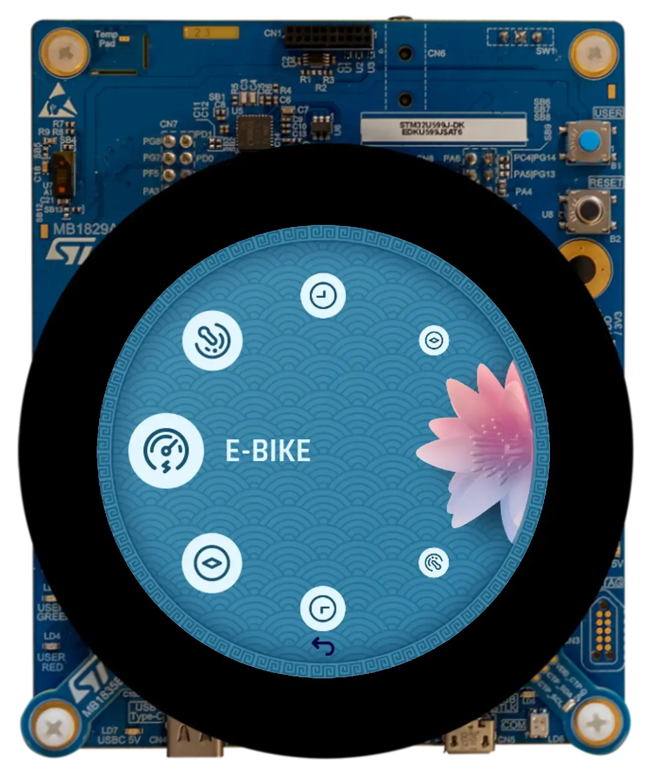
STM32U5A9 Discovery Board
The NeoChrom accelerator is known by the name GPU2D in source code and in STM32CubeMX.
NeoChrom and NeoChromVG
The NeoChrom accelerator has been updated with extra capabilities with the introduction of STM32U5G9. The improved accelerator is named NeoChromVG. The accelerator contains extended capabilities that allows hardware accelerated vector graphics.
| Micro controller | Accelerator |
|---|---|
| STM32U599/A9 | NeoChrom |
| STM32U5F7/G7 | NeoChromVG |
| STM32U5F9/G9 | NeoChromVG |
| STM32H7R7/S7 | NeoChrom |
| STM32N6 | NeoChrom |
NeoChrom Graphical Capabilities
The NeoChrom accelerators are capable of performing basic blitting (drawing images), blending, scaling, rotation, and texture mapping. All such operations are automatically used by TouchGFX when running on a microcontroller with NeoChrom.
Read more about the specific functionalities of NeoChrom here.
Vector Graphics
The new NeoChromVG accelerator can accelerate vector graphics. This capability is used when rendering SVG images with TouchGFX. An extra buffer called the stencil buffer is required by the GPU2D graphics accelerator. This buffer has the same dimension as the frame buffer, but only 1 byte pr pixel.
Example, if your frame buffer is 480 x 480 in 24bpp, the stencil buffer must be 480 * 480 = 230,400 bytes. It is important to allocate the stencil buffer in fast SRAM for best performance.
The stencil buffer is allocated by the TouchGFX Generator. See this guide.
Rendering Time Improvements with NeoChrom.
The following examples illustrate the speed-up provided by NeoChrom over DMA2D and software rendering. We have created two projects with the Designer. The first project shows an Image on a Box background. The second project shows a TextureMapper Widget on a Box background. The widget is redrawn in every frame. In both cases the bitmap is of size 128x128, in ARGB8888 format, and stored in the internal flash. The framebuffer is in RGB565 format.
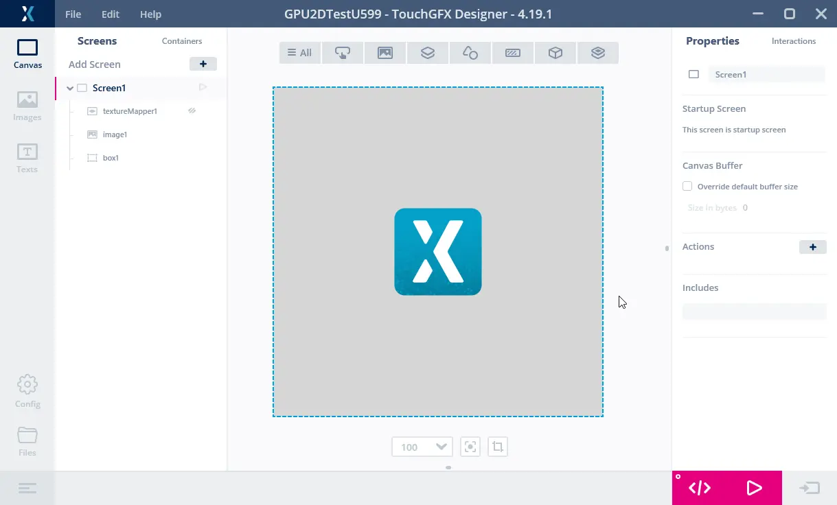
The Image project
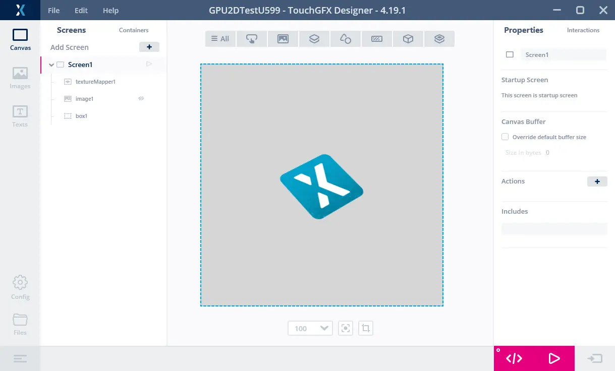
The TextureMapper project
Both projects have been executed on a STM32F746 and a STM32U5A9 Discovery board.
We have measured the rendering times by connecting a GPIO to a logic analyzer:

STM32F746 running the Image project
The figure above shows the frame rate and rendering time when running on the STM32F746. Channel 00 shows the VSYNC signal. We see that the display runs with a frame interval of 16.9 ms (A1 to A2) corresponding to a frame rate of 59.2 Hz. Channel 01 shows the render time (high when rendering, B1 to B2). The time to render the Image is thus 1.3 ms. Image rendering is fast on the STM32F746.

STM32F746 running the TextureMapper project
The figure above is the texture mapper project running on the STM32F746. The rendering time of the TextureMapper is 4.5 ms. The TextureMapper widget is much slower than the Image.

STM32U5A9 running the Image project
Here is the STM32U5A9 Discovery kit running the Image project. The STM32U5A9 Discovery kit display has a display frame interval of 12.26 ms corresponding to a frame rate of 81.6 Hz. The render time of the Image is 0.7 ms. We see that the Image widget is faster than on the STM32F746 kit.

STM32U5A9 running the TextureMapper project
The render time of the TextureMapper is 1.7 ms. The TextureMapper is also faster on STM32U5A9 than on the STM32F746.
Rendering Time Summary
The table below shows the rendering times:
| Element | STM32F746 | STM32U5A9 | Speed up |
|---|---|---|---|
| Frequency | 200 MHz | 160 MHz | 0.8 |
| Image | 1.3 ms | 0.7 ms | ~2x |
| TextureMapper | 4.5 ms | 1.7 ms | ~3x |
We see that even with a reduced clock frequency the STM32U5A9 greatly outperforms the STM32F746, especially with the TextureMapper.
These measurements are taken with the image in internal flash and the framebuffer in external SDRAM for STM32F746. The framebuffer is in internal SRAM for the STM32U5A9 (as this will be typical scenario). Moving the image to external flash hurts the STM32F746 as it uses QSPI flash (4-bit bus), whereas the STM32U5A9 uses a faster OSPI flash (8-bit bus).
The STM32F746 Discovery kit can run with a 480x272 RGB565 framebuffer in the internal RAM. This improves the performance (Image down to 1.03 ms), but it is not the standard configuration for STM32F746, as it uses a very large part of the internal SRAM for the frame buffer, leaving little RAM for other application components. Running with a single frame buffers is also not suitable for all applications.
Richer User Interfaces
The improved rendering performance can be used to create user interfaces with more advanced animations. For example more scaled or rotated elements. For the STM32F746, the display refresh time was 16.8 ms. This means that the application must keep the render time below this time to keep a frame rate of 60 fps. We can therefore have at most 3.75 texture mappers of that complexity (16.8 ms / 4.48 ms) on the screen, or a single larger texture mapper of size 247 x 247 (the same number of pixels and approximately the same rendering time). If we assume the same screen refresh rate, but use the STM32U5A9 CPU, we can have 14.36 texture mappers (16.8 ms / 1.17 ms), or a single texture mapper of size 485 x 485.
The following figure shows two applications running on respectively the STM32F746 and the STM32U5A9. The idea is to make a carousel-like menu where elements are scaled up when going to the center and scaled down when going out (here we just use the same texture for all the elements).
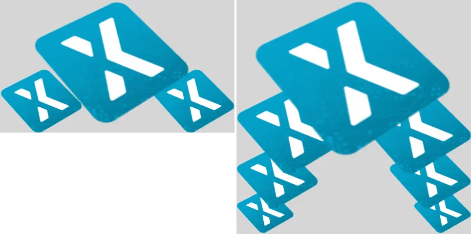
STM32F746 (left) with a 480x272 pixels display and STM32U5A9 (right) running the texture mapper based carousel project on a 480x480 display.
The STM32F746 is capable of showing three icons, one big icon, scaled up by a factor of 1.9, and two smaller icons. The STM32U5A9 is capable of showing 7 icons. The largest icon is scaled up by factor 2.7.
The rendering time of the application with 3 icons on the STM32F746 is 14.38 ms. The rendering time of the application with 7 icons on the STM32U5A9 is 14.93 ms. Both UIs can thus run in 60 fps, with the STM32U5A9 showing much more content in a higher resolution.
Accelerated Vector Graphics
The new NeoChromVG accelerator is capable of accelerating vector graphics. This open the possibilities of a new class of applications, where vector based graphics plays a central role and not bitmaps.
One example is a map-application. Maps can be built from bitmaps, but that often requires a very large storage or that specific map sections are downloaded in advance.
The video below shows a demonstration application running on a STM32U5G9. The application zooms, rotates, and pans a map that is drawn from a vector definition (multiple polygons that are filled with different colors and stroked). The video is running full screen on a 800 x 480 display with 16bpp colors.
STM32U5G9 showing a moving map.
SVG
NeoChrom GPU significantly improves SVG rendering performance. SVG rendering is partially accelerated with NeoChrom GPU and fully accelerated with NeoChromVG GPU. TouchGFX automatically leverages the available hardware.
The example below shows the performance improvements when using NeoChrom GPU. In the example, an SVG image of size 152x152 pixels is rendering on an STM32F746 (software rendering), an STM32H7S7 and an STM32N657 (NeoChrom GPU), and an STM32U5G9 (NeoChromVG GPU).

Simple SVG drawing in size 152 x 152 pixels.
The render time of the SVG image is shown in the table below:
| MCU | Accelerator | Render time | Hardware | Core frequency | Framebuffer strategy |
|---|---|---|---|---|---|
| STM32F746 | Chrom-ART | 4.12 ms | STM32F746G-DK | 216 MHz | Double in external SDRAM |
| STM32U5G9 | NeoChromVG | 0.97 ms | STM32U5G9J-DK2 | 160 MHz | Double in internal SRAM |
| STM32H7S8 | NeoChrom | 2.80 ms | STM32H7S78-DK | 600 MHz | Double in external PSRAM |
| STM32N657 | NeoChrom | 0.78 ms | STM32N6570-DK | 800 MHz | Double in internal SRAM |
The measurements are performed using the TBSs available in TouchGFX Designer, using their default configuration. On the STM32H7S78-DK and STM32N6570-DK the GPU is driven at half the core frequency. On the STM32U5G9J-DK2 the GPU is running at the core frequency. As a result, the table shows that the STM32N657 is rendering the SVG faster than the STM32U5G9 despite the latter having NeoChromVG GPU. This difference mainly due to GPU frequency rather than inherent GPU capability: when GPU frequency is taken into account, NeoChromVG GPU remains faster and more efficient for vector rendering compared to NeoChrom GPU — and both outperform pure software rendering.
Further reading
Read more about using SVG in TouchGFX here: SVG.
Vector fonts
The NeoChrom and NeoChromVG also accelerates drawing of vector fonts. You can read more about how to use vector fonts in this article: Vector fonts.
Creating a project
CubeMX and the TouchGFX Generator supports the NeoChrom. In STM32CubeMX the accelerator is known by its code name GPU2D. The GPU2D accelerator is only available to TouchGFX if GPU2D is enabled in the TouchGFX configuration in STM32CubeMX. If you use any of the TouchGFX TBS's (template projects) provided with the TouchGFX Designer this is already done. If you make your own custom project, make sure to enable the GPU2D Accelerator as shown below:
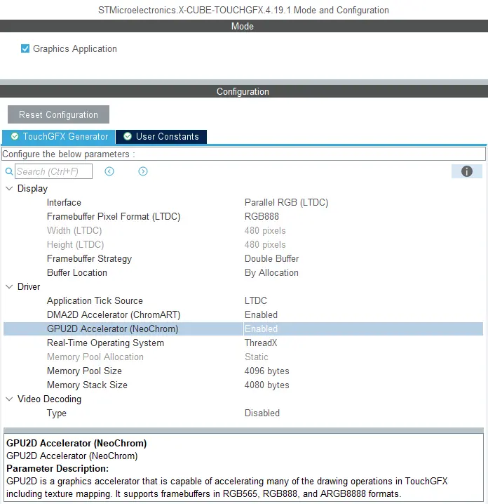
Enabling GPU2D (NeoChrom GPU) in STM32CubeMX
After enabling GPU2D press "Generate Code" in STM32CubeMX. This regenerates the target configuration code. Now open the project in the TouchGFX Designer and generate code there also (F4).
TouchGFX Designer generates assets (images, fonts, and texts) and simulator code, that matches the target configuration. You are now ready to compile the code.
If you are starting a project from TouchGFX Designer there is no need to open STM32CubeMX unless you need to change some hardware settings.
Framebuffer Formats
The NeoChrom GPU does not natively support all color formats on all MCUs. The supported frambuffer formats can be seen in the table below:
| Micro controller | RGB565 (16 bpp) | RGB888 (24 bpp) | ARGB8888 (32 bpp) |
|---|---|---|---|
| STM32U5x7/x9 | Natively | Natively | Natively |
| STM32H7R7/S7 | Natively | Using GFXMMU* | Natively |
| STM32N6 | Natively | Not supported* | Natively |
* These limitations are described in the following chapter.
STM32H7R7/S7 and STM32N6 limitations when using RGB888 framebuffer (24 bpp)
The internal bus to the NeoChrom GPU in STM32H7R7/S7 and STM32N657 does not support 24 bpp. At the moment there is no workaround for STM32N6, but for STM32H7R7/S7 it is possible to use the GFXMMU to achieve 24 bpp framebuffers. In this scenario, the GFXMMU is used to convert 32 bpp rendering to 24 bpp framebuffers. This means that TouchGFX runs as if it was a 32 bpp framebuffer and then the GFXMMU converts the pixel data when writing it to the 24 bpp framebuffer. To see an example of this setup, you can download the STM32H7S78_24bpp TBS from TouchGFX Designer, which uses the GFXMMU setup to enable 24 bpp framebuffer. Be aware that when using this setup it is not possible to have opaque image assets in RGB888. Instead you must select ARGB8888 as your opaque image format to utilize the full color depth of your 24 bpp framebuffer.
Step-by-step guide to enable 24 bpp framebuffers on STM32H7R7/S7
This guide provides step-by-step instructions on how to convert a project for STM32H7R7/S7 to use 24 bpp framebuffers. It assumes that the steps are implemented on an already working project with 16 bpp framebuffers. If the steps are followed on a project with 32 bpp framebuffers, step 6 can be skipped.
- Open STM32CubeMX and activate the GFXMMU for the Application context. The GFXMMU is found under the Multimedia tab.
- Enable two packing buffers and select GFXMMU_PACKING_MSB_REMOVE as the packing mode for both. One buffer is needed per framebuffer, so for a single framebuffer setup, only one buffer is needed.
Note: If you use emulated framebuffer, the first buffer is reserved for this. Therefore, you cannot use the first buffer for the 32 bpp to 24 bpp conversion if you are also using emulated framebuffer. - Set the physical addresses of the buffers enabled above. The physical address is where the 24 bpp framebuffer is placed in RAM.
- Set default alpha to 0xFF.
- Open Layer Settings in the LTDC configuration, which is also found under the Multimedia tab.
- Set Layer 0 - Pixel Format to ARGB8888.
- Set Layer 0 - Color Frame Buffer Start Address to one of the GFXMMU virtual buffers.
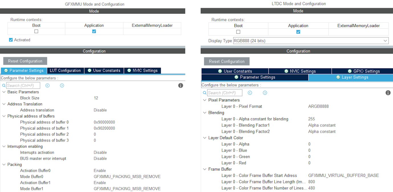
Example of GFXMMU and LTDC configuration for STM32H7S78-DK with 24 bpp framebuffers
- Open X-CUBE-TOUCHGFX, which is found under Middleware and Software Packs.
- Set Buffer Location to By Address and write GFXMMU_VIRTUAL_BUFFERx_BASE in the start addresses. Replace 'x' with the numbers of the packing buffers selected in step 2.
- Generate code in STM32CubeMX.
- Add the following code to the MX_LTDC_Init function in main.c to override the image format setting for the LTDC:
/* USER CODE BEGIN LTDC_Init 2 */
// Reconfigure pixelformat since TouchGFX project generator does not allow setting different format for LTDC and
// remaining configuration. This way TouchGFX runs 32BPP mode but the LTDC accesses the real framebuffer in 24BPP
pLayerCfg.PixelFormat = LTDC_PIXEL_FORMAT_RGB888;
if (HAL_LTDC_ConfigLayer(&hltdc, &pLayerCfg, 0) != HAL_OK)
{
  Error_Handler();
}
/* USER CODE END LTDC_Init 2 */ - Open TouchGFXHAL.cpp, which is found in the project directory under TouchGFX/target.
- Add include of HAL file for the MCU if not already present. For STM32H7R7/S7 that would be:
#include "stm32h7rsxx_hal.h" - Make the handle for the GFXMMU available by adding the line:
extern GFXMMU_HandleTypeDef hgfxmmu; - Declare a pointer to the virtual framebuffer. For example:
static uint16_t* tft = 0; - Change the implementation of TouchGFXHAL::setTFTFrameBuffer to give the true framebuffer address to the TFT LTDC controller while TouchGFX framework uses the virtual address through the GFXMMU. Assuming the packing buffers used are buffer 0 and 1, the implementation should be like this:
void TouchGFXHAL::setTFTFrameBuffer(uint16_t* address)
{
    tft = address;
    if (tft == (uint16_t*)GFXMMU_VIRTUAL_BUFFER0_BASE)
    {
        TouchGFXGeneratedHAL::setTFTFrameBuffer((uint16_t*)hgfxmmu.Init.Buffers.Buf0Address);
    }
    else
    {
        TouchGFXGeneratedHAL::setTFTFrameBuffer((uint16_t*)hgfxmmu.Init.Buffers.Buf1Address);
    }
} - Change the implementation of TouchGFXHAL::getTFTFrameBuffer() to
uint16_t* TouchGFXHAL::getTFTFrameBuffer() const
{
    return tft;
} - Open the project in TouchGFX Designer.
- Go to Config -> Default Image Configuration and select ARGB8888 as the Opaque Image Format.
- Generate code in TouchGFX Designer.
The project will now run with 24 bpp framebuffers, but TouchGFX will still render in 32 bpp. As a result, the performance will naturally be worse compared to 16 bpp and native 24 bpp. However, since native 24 bpp is not an option on STM32H7R7/S7, this is the best available solution when 24 bpp is required.
STM32U5 limitations when having framebuffer(s) in external RAM
The NeoChrom accelerator on the STM32U5 MCU family does not integrate dedicated write buffers to enable high efficiency when writing to external memories. As a consequence, the NeoChrom accelerator does a lot of "small" writes to the bus where the external memory is connected. This can lead to bus contention issues with the diplay controller which reads pixels on the same bus. Therefore, it is recommended to only have framebuffers in internal RAM when using the NeoChrom accelerator on STM32U5. If framebuffer must be in external RAM, it is recommended to not use the NeoChrom accelerator. The Chrom-ART accelerator can still be used.
Texture Cache
The STM32U5 MCU family with the NeoChrom accelerator uses a second data cache (DCACHE2) to optimize the access to texture in external RAM. This cache can also cache the internal SRAM. This is the default behavior for the second data cache.
There is generally no big benefit of caching the SRAM (it is already fast) and it is better to reserve the cache for the slower external memories (OSPI flash). Caching also requires cache maintenance operations (cache invalidation) to be performed when the CPU writes to the cached areas of SRAM.
For these reasons TouchGFX assumes that caching of SRAM is disabled for the second cache.
Since version 6.11 CubeMX generates these lines:
static void MX_DCACHE2_Init(void)
{
  hdcache2.Instance = DCACHE2;
  hdcache2.Init.ReadBurstType = DCACHE_READ_BURST_INCR;
  if (HAL_DCACHE_Init(&hdcache2) != HAL_OK)
  {
    Error_Handler();
  }
   __HAL_RCC_SYSCFG_CLK_ENABLE();
   HAL_SYSCFG_DisableSRAMCached();
}
Make sure you have the two last lines, if you do not use CubeMX.
NeoChrom Limitations
The NeoChrom and NeoChromVG graphics accelerators does not support the L8 image formats (L8_RGB565, L8_RGB888, L8_ARGB8888) with TouchGFX. If you use these image formats in a TouchGFX application running on either of the micro controllers with NeoChrom/NeoChromVG the images will be drawn using DMA2D. If you use these formats with ScalableImage or TextureMapper a software fall-back will be used.
It is therefore recommended to not use L8 images with micro controllers with NeoChrom/NeoChromVG accelerators.
The NeoChrom graphics accelerator creates suboptimal anti-aliasing on graphics elements drawn with the "Non-zero fill-rule" compared to NeoChromVG. This may happen with SVG files that can specify the fill-rule as "nonzero". A work-around is to use "evenodd" fill-rule, but it is not valid for all drawings.