Running graphics from external RAM
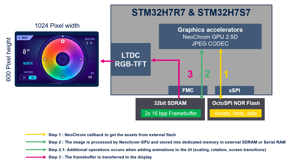
This section describes how to calculate the graphics performance of a typical setup illustrated below. The example is a high resolution 24bit RGB-TFT display at 1024x600 pixels with 16bpp framebuffers stored in external 32bit SDRAM. The graphical assets are stored in an external OSPI NOR flash.
Objective
- Provide a step-by-step overview for developers to better understand and estimate their system performance for a graphical user interface application.
- Check if the selected display and its requirements can be sustained by the defined specified system.
- Understand how complex a GUI it would be possible to develop within the subsystem defined.
Step 1: Display specifications
The display used on the STM32H7S78 Discovery Kit is the MB1860. Link to BoM for the Discovery Kit can be found here. The display on the Discovery Kit has a resolution of 800px x 480px, which is lower than the resolution used in this example. The display specifications for the example can be seen below:
- Display height: 600px
- Display width: 1024px
- Display refresh rate: 60Hz
- Display blanking area*: Typically ~10%
*Display blanking covers the sum of inactive pixels. The main contribution is the porches for the LTDC.
Step 2: Display requirements and pixel clock calculations
At this step we need to calculate the display requirements, to understand if our MCU and memory selection can operate the display under the needed specifications.
From the display size specified above, we know that the total number of pixels is:
pixel height x pixel width = 600px x 1024px = 614.400px
The display has a refresh rate of (1000ms / 60 = 16ms) 60Hz, so the LTDC needs to fetch the framebuffer and send it to the display approximately every 16ms. The system (RAM) bandwidth required to keep the display updated at 60Hz (average, without blanking) can then be found with the following formula:
display pixels x update frequency x framebuffer color depth (RGB565)
614.400px x 60Hz x 16bpp = 589.824.000bits/sec = 589,82Mbit/sec
The pixel clock required to update the display at 60Hz can be found with the calculation below.
(total number of pixels x refresh rate x (blanking% / 100 + 1)) / 1.000.000.
(614.400px x 60Hz x (10 / 100 + 1)) / 1.000.000 = 40,55 MHz pixel clock
Caution
It is important not to exceed the maximum pixel clock supported by the LTDC. Check the LTDC application note, AN4861, for an overview of the maximum supported pixel clock in different configurations. An overview of maximum pixel clock for STM32H7R/S can be found in table 13.
An overview of the maximum supported pixel clock for STM32H7R/S can be found in table 13 of the LTDC application note, which is inserted below.
Step 3: Framebuffer and memory strategy
In this example, we use an external 32-bit SDRAM connected to a 32-bit wide FMC interface running at 100MHz, employing a double framebuffer strategy. Alternatively, developers can use 16bit SDRAM, 4/8/16 bit Serial RAMs like Hyper RAM and Serial PSRAM at 200MHz DTR also.
For all external memories some extra cycles are needed to start the operations, and for this example we take the assumption that the SDRAM is working at ~80% efficiency.
Step 4: Framebuffer performance
The theoretical RAM throughput is given by the following equation, when front and back buffer is placed at different RAM banks:
interface width x interface frequency = Mbit/sec
32bit x 100MHz = 3.200Mbit/sec = 400MB/Sec
However, this throughput is based on the RAM being 100% efficient. If we consider the estimated efficiency from step 3, the actual throughput is:
3.200Mbit/sec x 0.8 = 2.560Mbit/sec = 320Mbytes/sec
Step 5: Calculating remaining bandwidth after a display update
Earlier we saw that the display required 589,82Mbit/sec, and that our external RAM has a throughput of 2.560Mbit/sec. Now let us check how much is left for the screen rendering/animations.
2.560Mbit/sec – 589,82Mbit/sec = 1.970,18Mbit/sec = 246,27MBytes/sec
Overall, the example system can keep the display updated and on top of this there is also ~1.970Mbit/sec remaining bandwidth for extra animations and more UI layers.
Step 6: UI Rendering performance (GUI FPS)
In this UI case, we are targeting 60FPS GUI rendering. This means the system must render and transfer a new frame within 16ms. Additionally, we can accept a drop to 30FPS for some advanced UI animations, ensuring a fluid user experience throughout.
Let’s calculate the framebuffer performance per framebuffer slice, meaning how many Mbit can we render inside each frame (per 16ms). First, we use the remaining framebuffer bandwidth (1.970Mbit/sec) and divide by 60FPS.
1.970Mbit/sec / 60FPS = 32,8Mbit per frame (approximately every 16ms at 60FPS).
This means that the RAM throughput is 32,8Mbit per 16ms to render and update the UI.
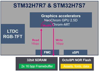
Step 2 in the setup illustration in the beginning shows a possible extra rendering for altering/updating the UI. Since the framebuffers are 16bpp, all operations on the framebuffers are done in 16bpp. Writing a pixel in the framebuffer will hence acquire 16bits of the SDRAM bandwidth. If a pixel needs to be blended, the pixel will first be read from the framebuffer by NeoChrom GPU. After the pixel is blended (modified), it will be written back to the framebuffer. This means that the system needs to transfer 16bits twice for a read-modify-write operation resulting in a use of 16bit + 16bit = 32bit of the SDRAM bandwidth as illustrated in the image below.
We can now calculate how many pixels we can perform one operation on within each frame:
32,8Mbit/frame / 16bpp = 2,05Mpixels
To give a reference point, we calculate how many full screen operations it is possible to do within each frame:
2,05Mpixels / 614.000px = 3,34 times
This means that we can for example draw a full-screen box and then blend it with another box (16bpp write + 16bpp read + 16bpp write). This could further be blended with a third box covering 34% / 2 = 17% of the screen.
As mentioned at the beginning of step 6, we can accept a drop to 30FPS for some advanced UI animations. This means that we have twice the available bandwidth compared to 60FPS, resulting in the following number of full-screen operations possible within each frame:
3,34 x 2 = 6,68 times
It cannot be said unequivocally how many full-screen operations it should be possible to do within each frame, as it heavily depends on the complexity of the UI. Furthermore, it is important to consider if the external RAM is required for anything else than framebuffers. However, a reasonable guideline for many applications is that it should be at least above 3 times.
To compare with a concrete example, the STM32H7S78-DK runs an 800x480 RGB TFT display, with 16bit framebuffers in external 16bit serial PSRAM at 200MHz DTR (800MB/S theoretically if 100% efficient). This type of memory protocol uses more cycles initially resulting in a lower memory initialization efficiency compared to SDRAM (See AN6062 for more details on serial RAM performance). The above example and calculations show that, at this resolution, even most complex UIs can be rendered while maintaining 60 FPS.
Another reference is the TouchGFX Demo showing a complex UI with 2 different RAM and Flash memory frequencies.
Further reading
Note
It is important to note that the calculations above do not consider the available computing power; they solely focus on the RAM bandwidth. Additionally, the calculations are based on assumptions regarding the RAM efficiency. While these assumptions are not arbitrary, they remain assumptions, nonetheless.
Despite these limitations, the procedure in the example can still serve as an indication of possible performance.
Glossary
- Read-modify-write: A process where a memory location is read, modified, and then written back.
- Pixel clock: The frequency at which pixels are transmitted to the display, determining the refresh rate and resolution of the screen. It defines the speed at which the display controller sends pixel data to the display panel.
- Framebuffer: An area in RAM containing a bitmap that drives the display. The framebuffer stores pixel values, which are read by the display controller. The rendering operations are performed to the framebuffer.
- Blanking: Display blanking covers the sum of inactive pixels. The main contribution is the porches for the LTDC.
- FMC: Flexible Memory Controller. A hardware component that manages the interface between the CPU and various types of memory, such as SRAM, NOR, NAND, and SDRAM. In this example it is used for the external SDRAM.
- XSPI: Extended-SPI interface. An advanced version of SPI that supports higher data rates and additional features for enhanced communication with peripheral devices. In this example it is used for the external NOR flash. For more information visit the wiki.
- Memory protocol overhead: The extra time and resources required to manage communication and data transfer between memory and the processor, including tasks like error checking, handshaking, and addressing. This overhead impacts the overall system performance.
- DTR: Double Transfer Rate. Data is transferred on both rising and falling clock edges. The bandwith is hence doubled.

