NeoChrom/NeoChromVG在TouchGFX中的应用
This section discusses how to use TouchGFX on hardware having the NeoChrom GPU graphics accelerator. 该图形加速器显著提高了纹理映射、图像缩放和旋转等操作的性能。 这意味着可以在保持高帧速率的同时构建更高级的UI。
The NeoChrom graphics accelerator is currently available in STM32U5x7, STM32U5x9, STM32H7R7/S7 and STM32N6 microcontrollers. 所有系列均提供对应的开发板。
STM32U5A9探索板
The NeoChrom accelerator is known by the name GPU2D in source code and in STM32CubeMX.
NeoChrom和NeoChromVG
随着STM32U5G9的推出,NeoChrom加速器更新了额外的功能。 改良版加速器命名为NeoChromVG。 加速器包含允许硬件加速矢量图形的扩展功能。
| 微控制器 | 加速器 |
|---|---|
| STM32U599/A9 | NeoChrom |
| STM32U5F7/G7 | NeoChromVG |
| STM32U5F9/G9 | NeoChromVG |
| STM32H7R7/S7 | NeoChrom |
| STM32N6 | NeoChrom |
NeoChrom图形功能
NeoChrom加速器能够执行基本的blitting(绘制图像)、混合、缩放、旋转和纹理映射。 有NeoChrom的微控制器上运行时,TouchGFX会自动使用所有操作。
Read more about the specific functionalities of NeoChrom here.
矢量图形
新型NeoChromVG加速器可加速矢量图形。 使用TouchGFX渲染SVG图像时使用此功能。 GPU2D图形加速器需要一个称为模板缓冲区的额外缓冲区。 该缓冲区具有与帧缓存相同的尺寸,但每像素只有1字节。
例如,对于分辨率480x480,色深24bpp的帧缓存,则模板缓冲区必须为480*480=230,400字节。 为了获得最佳性能,最好是把模板缓冲区放在内部SRAM中。
模版缓冲区由ToughGFX 生成器分配。 请参阅 本 指南。
使用NeoChrom改善渲染时间.
以下示例说明NeoChrom在DMA2D和软件渲染方面提供的加速。 我们利用设计器创建了两个项目。 第一个项目是在方框背景上显示Image。 第二个项目在Box背景上显示TextureMapper Widget。 控件在每一帧中都会重新绘制。 这两种情况下,位图大小为128x128,采用ARGB888格式,并存储在内部Flash中。 帧缓存采用RGB565格式。
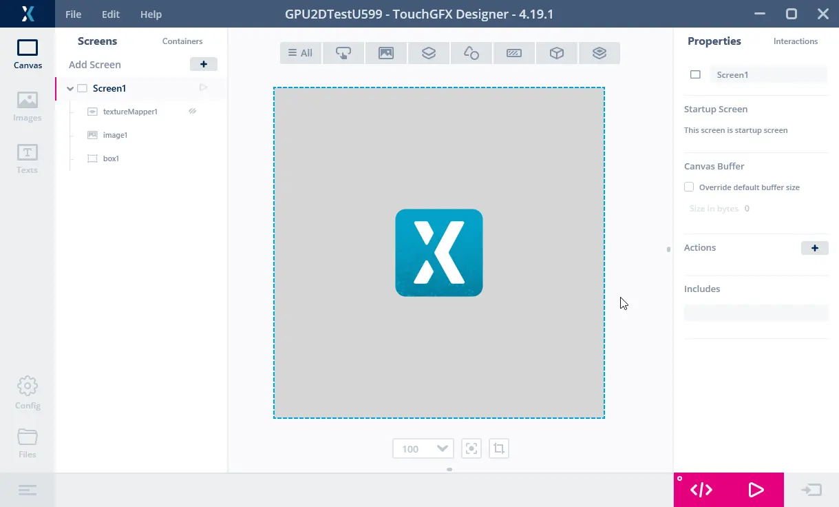
Image项目
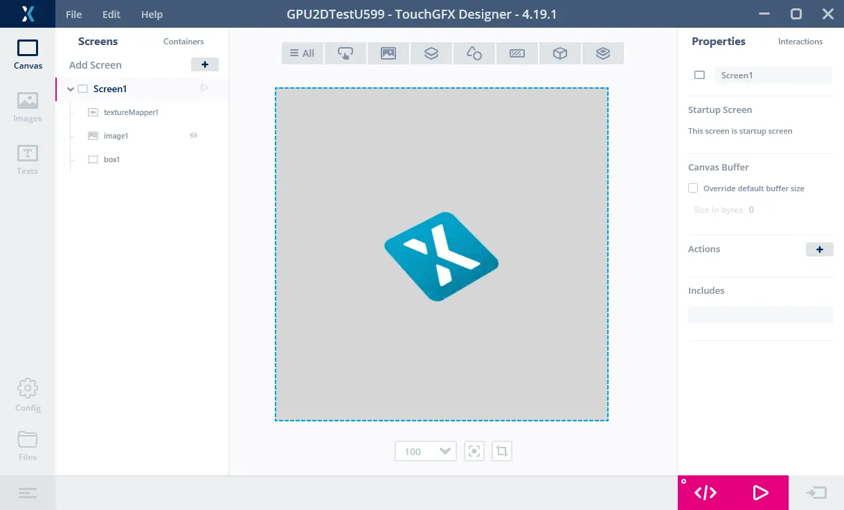
TextureMapper项目
两个项目在STM32F746和STM32U5A9探索板上执行。
我们将GPIO连接到逻辑分析仪来测量渲染时间:

STM32F746运行Image项目
上图显示了在STM32F746上运行时的帧速率和渲染时间。 通道00显示VSYNC信号。 我们看到,显示器以16.9ms(A1至A2)的帧间隔运行,对应59.2Hz帧速率。 通道01显示渲染时间(渲染时较高,B1到B2)。 因此,渲染Image的时间为1.3 ms。 STM32F746上的Image渲染速度快。

STM32F746运行TextureMapper项目
上图为STM32F746上运行的TextureMapper项目。 TextureMapper的渲染时间为 4.5 ms。 TextureMapper控件比Image慢得多。

STM32U5A9运行Image项目
此为运行Image项目的STM32U5A9探索套件。 STM32U5A9探索套件显示屏的显示帧间隔为12.26 ms,对应81.6 Hz帧速率。 Image的渲染时间为 0.7 ms。 我们看到Image控件比STM32F746套件更快。

STM32U5A9运行TextureMapper项目
TextureMapper的渲染时间为 1.7 ms。 与STM32F746相比,STM32U5A9上的TextureMapper速度更快。
渲染时间总结
下表显示了渲染时间:
| 元素 | STM32F746 | STM32U5A9 | 加快 |
|---|---|---|---|
| 频率 | 200 MHz | 160 MHz | 0.8 |
| 图像 | 1.3 ms | 0.7 ms | ~2x |
| TextureMapper | 4.5 ms | 1.7 ms | ~3x |
我们看到,即使时钟频率降低,STM32U599也大大优于STM32F746,TextureMapper尤为如此。
对于STM32F746,使用内部闪存中的图像和外部SDRAM中的帧缓存进行此类测量。 STM32U5A9的帧缓冲器位于内部SRAM中(此为典型应用场景)。 将图像放在外部Flash对比会更加降低STM32F746性能,因其使用QSPI Flash(4位总线),而STM32U5A9使用更快的OSPI Flash(8位总线)。
STM32F746 Discovery套件可在内部RAM中使用480x272 RGB565帧缓存运行。 从而提高了性能(Image降至1.03ms),但其并非STM32F746的标准配置,因为它使用了很大一部分内部SRAM作为帧缓存,只剩下很少的RAM用于其他应用程序组件。 利用单帧缓存运行也不适用于所有应用程序。
更丰富的用户界面
改进的渲染性能可用于创建具有更高级动画的用户界面。 例如,更多缩放或旋转元素。 对于STM32F746,显示器刷新时间为16.8ms。 这意味着应用程序必须将渲染时间保持在该时间以下,以保持60fps的帧速率。 因此,屏幕上最多可以有3.75个此种复杂度(16.8毫秒/4.48毫秒)的纹理映射器,或者一个尺寸为247 x 247(像素数量相同,渲染时间大致相同)的较大纹理映射器。 如果我们假设屏幕刷新率相同,但使用STM32U5A9 CPU,则可以有14.36个纹理映射器(16.8毫秒/1.17毫秒),或一个485 x 485大小的单个纹理映射器。
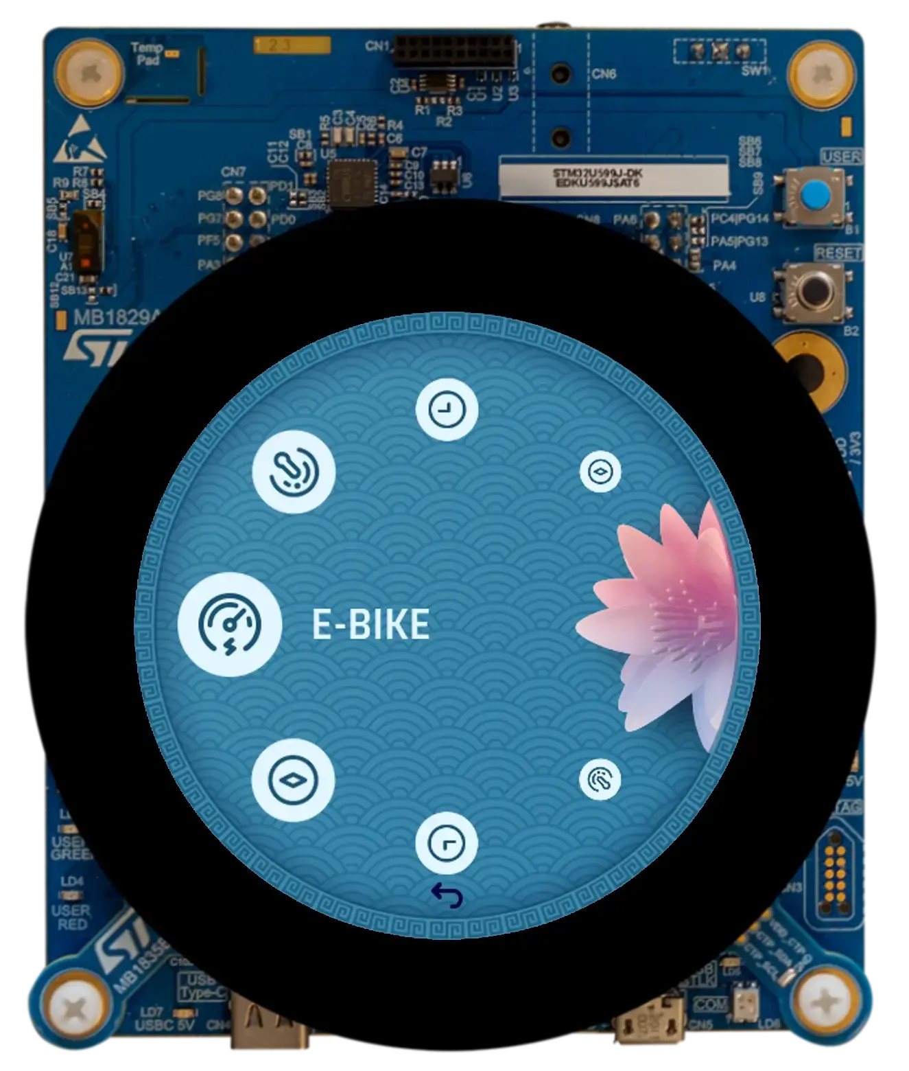
下图显示了分别在STM32F746和STM32U5A9上运行的两个应用程序。 其想法是制作一个类似旋转木马的菜单,其中元素在到达中心时被放大,离开时被缩小(这里我们对所有元素使用相同的纹理)。
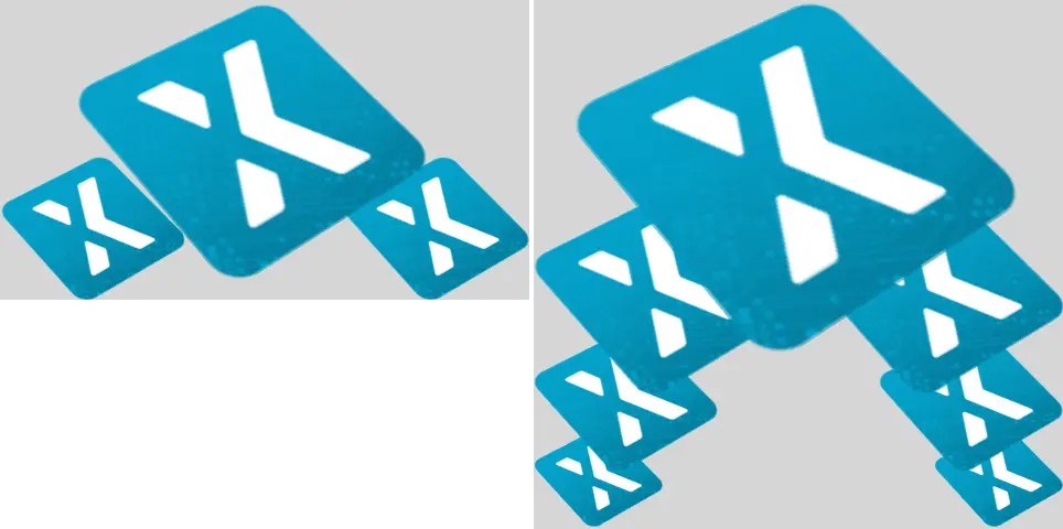
STM32F746(左)具有480x272像素显示屏,STM32U5A9(右)在480x480显示屏上运行基于纹理映射器的轮播项目。
STM32F746能够显示三个图标,一个放大1.9倍的大图标和两个较小的图标。 STM32U5A9能显示7个图标。 最大的图标放大了2.7倍。
STM32F746上3图标应用程序的渲染时间为14.38 ms。 STM32U5A9上7图标应用程序的渲染时间为14.93ms。 因此,两种UI均能以60 fps的速度运行,STM32U5A9以更高的分辨率显示更多内容。
加速矢量图形
新型NeoChromVG加速器可加速矢量图形。 该功能开启了新型应用程序的可能性,其中基于矢量的图形起着核心作用,而非位图。
地图应用程序便是一个例子。 地图可以从位图中构建,但这通常需要非常大的存储空间,或者需要提前下载特定的地图部分。
以下视频显示了STM32U5G9上运行的演示应用程序。 该应用可对由矢量定义绘制的地图进行缩放、旋转和平移(用不同颜色填充并描边的多个多边形)。 视频在800 x 480的16bpp彩色显示屏上全屏播放。
STM32U5G9显示移动地图。
SVG
NeoChrom GPU significantly improves SVG rendering performance. SVG rendering is partially accelerated with NeoChrom GPU and fully accelerated with NeoChromVG GPU. TouchGFX automatically leverages the available hardware.
The example below shows the performance improvements when using NeoChrom GPU. In the example, an SVG image of size 152x152 pixels is rendering on an STM32F746 (software rendering), an STM32H7S7 and an STM32N657 (NeoChrom GPU), and an STM32U5G9 (NeoChromVG GPU).

尺寸为152 x 152像素的简单SVG绘图。
SVG图像的渲染时间如下表所示:
| MCU | 加速器 | Render time | Hardware | Core frequency | Framebuffer strategy |
|---|---|---|---|---|---|
| STM32F746 | Chrom-ART | 4.12 ms | STM32F746G-DK | 216 MHz | Double in external SDRAM |
| STM32U5G9 | NeoChromVG | 0.97 ms | STM32U5G9J-DK2 | 160 MHz | Double in internal SRAM |
| STM32H7S8 | NeoChrom | 2.80 ms | STM32H7S78-DK | 600 MHz | Double in external PSRAM |
| STM32N657 | NeoChrom | 0.78 ms | STM32N6570-DK | 800 MHz | Double in internal SRAM |
The measurements are performed using the TBSs available in TouchGFX Designer, using their default configuration. On the STM32H7S78-DK and STM32N6570-DK the GPU is driven at half the core frequency. On the STM32U5G9J-DK2 the GPU is running at the core frequency. As a result, the table shows that the STM32N657 is rendering the SVG faster than the STM32U5G9 despite the latter having NeoChromVG GPU. This difference mainly due to GPU frequency rather than inherent GPU capability: when GPU frequency is taken into account, NeoChromVG GPU remains faster and more efficient for vector rendering compared to NeoChrom GPU — and both outperform pure software rendering.
Further reading
Read more about using SVG in TouchGFX here: SVG.
矢量字体
NeoChrom和NeoChromVG还可加速矢量字体的绘制。 您可在本文中阅读更多有关如何使用矢量字体的信息: 矢量字体。
创建项目
CubeMX和TouchGFX Generator支持NeoChrom。 In STM32CubeMX the accelerator is known by its code name GPU2D. The GPU2D accelerator is only available to TouchGFX if GPU2D is enabled in the TouchGFX configuration in STM32CubeMX. 如果您使用TouchGFX设计器提供的任意TouchGFX TBS(模板项目),则已完成启用。 如果您创建自己的定制项目,请确保启用GPU2D加速器,如下所示:
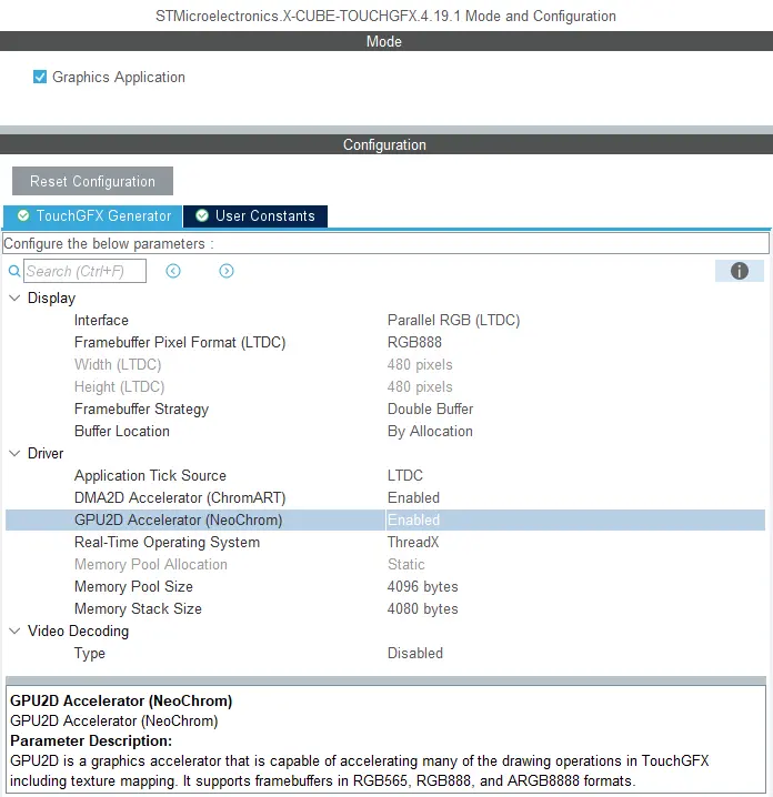
Enabling GPU2D (NeoChrom GPU) in STM32CubeMX
After enabling GPU2D press "Generate Code" in STM32CubeMX. 重新生成目标配置代码。 然后,在TouchGFX 设计器中打开项目并在那里生成代码(F4)。
TouchGFX Designer generates assets (images, fonts, and texts) and simulator code, that matches the target configuration. 现在,您可以编译代码。
If you are starting a project from TouchGFX Designer there is no need to open STM32CubeMX unless you need to change some hardware settings.
帧缓存格式
The NeoChrom GPU does not natively support all color formats on all MCUs. The supported frambuffer formats can be seen in the table below:
| 微控制器 | RGB565 (16 bpp) | RGB888 (24 bpp) | ARGB8888 (32 bpp) |
|---|---|---|---|
| STM32U5x7/x9 | Natively | Natively | Natively |
| STM32H7R7/S7 | Natively | Using GFXMMU* | Natively |
| STM32N6 | Natively | Not supported* | Natively |
* These limitations are described in the following chapter.
STM32H7R7/S7 and STM32N6 limitations when using RGB888 framebuffer (24 bpp)
The internal bus to the NeoChrom GPU in STM32H7R7/S7 and STM32N657 does not support 24 bpp. At the moment there is no workaround for STM32N6, but for STM32H7R7/S7 it is possible to use the GFXMMU to achieve 24 bpp framebuffers. In this scenario, the GFXMMU is used to convert 32 bpp rendering to 24 bpp framebuffers. This means that TouchGFX runs as if it was a 32 bpp framebuffer and then the GFXMMU converts the pixel data when writing it to the 24 bpp framebuffer. To see an example of this setup, you can download the STM32H7S78_24bpp TBS from TouchGFX Designer, which uses the GFXMMU setup to enable 24 bpp framebuffer. Be aware that when using this setup it is not possible to have opaque image assets in RGB888. Instead you must select ARGB8888 as your opaque image format to utilize the full color depth of your 24 bpp framebuffer.
Step-by-step guide to enable 24 bpp framebuffers on STM32H7R7/S7
This guide provides step-by-step instructions on how to convert a project for STM32H7R7/S7 to use 24 bpp framebuffers. It assumes that the steps are implemented on an already working project with 16 bpp framebuffers. If the steps are followed on a project with 32 bpp framebuffers, step 6 can be skipped.
- Open STM32CubeMX and activate the GFXMMU for the Application context. The GFXMMU is found under the Multimedia tab.
- Enable two packing buffers and select GFXMMU_PACKING_MSB_REMOVE as the packing mode for both. One buffer is needed per framebuffer, so for a single framebuffer setup, only one buffer is needed.
Note: If you use emulated framebuffer, the first buffer is reserved for this. Therefore, you cannot use the first buffer for the 32 bpp to 24 bpp conversion if you are also using emulated framebuffer. - Set the physical addresses of the buffers enabled above. The physical address is where the 24 bpp framebuffer is placed in RAM.
- Set default alpha to 0xFF.
- Open Layer Settings in the LTDC configuration, which is also found under the Multimedia tab.
- Set Layer 0 - Pixel Format to ARGB8888.
- Set Layer 0 - Color Frame Buffer Start Address to one of the GFXMMU virtual buffers.
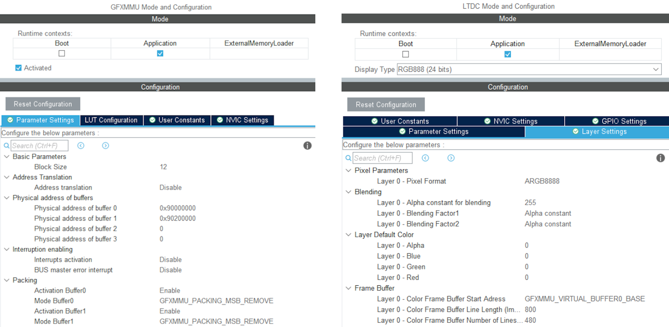
Example of GFXMMU and LTDC configuration for STM32H7S78-DK with 24 bpp framebuffers
- Open X-CUBE-TOUCHGFX, which is found under Middleware and Software Packs.
- Set Buffer Location to By Address and write GFXMMU_VIRTUAL_BUFFERx_BASE in the start addresses. Replace 'x' with the numbers of the packing buffers selected in step 2.
- Generate code in STM32CubeMX.
- Add the following code to the MX_LTDC_Init function in main.c to override the image format setting for the LTDC:
/* USER CODE BEGIN LTDC_Init 2 */
// Reconfigure pixelformat since TouchGFX project generator does not allow setting different format for LTDC and
// remaining configuration. This way TouchGFX runs 32BPP mode but the LTDC accesses the real framebuffer in 24BPP
pLayerCfg.PixelFormat = LTDC_PIXEL_FORMAT_RGB888;
if (HAL_LTDC_ConfigLayer(&hltdc, &pLayerCfg, 0) != HAL_OK)
{
  Error_Handler();
}
/* USER CODE END LTDC_Init 2 */ - Open TouchGFXHAL.cpp, which is found in the project directory under TouchGFX/target.
- Add include of HAL file for the MCU if not already present. For STM32H7R7/S7 that would be:
#include "stm32h7rsxx_hal.h" - Make the handle for the GFXMMU available by adding the line:
extern GFXMMU_HandleTypeDef hgfxmmu; - Declare a pointer to the virtual framebuffer. For example:
static uint16_t* tft = 0; - Change the implementation of TouchGFXHAL::setTFTFrameBuffer to give the true framebuffer address to the TFT LTDC controller while TouchGFX framework uses the virtual address through the GFXMMU. Assuming the packing buffers used are buffer 0 and 1, the implementation should be like this:
void TouchGFXHAL::setTFTFrameBuffer(uint16_t* address)
{
    tft = address;
    if (tft == (uint16_t*)GFXMMU_VIRTUAL_BUFFER0_BASE)
    {
        TouchGFXGeneratedHAL::setTFTFrameBuffer((uint16_t*)hgfxmmu.Init.Buffers.Buf0Address);
    }
    else
    {
        TouchGFXGeneratedHAL::setTFTFrameBuffer((uint16_t*)hgfxmmu.Init.Buffers.Buf1Address);
    }
} - Change the implementation of TouchGFXHAL::getTFTFrameBuffer() to
uint16_t* TouchGFXHAL::getTFTFrameBuffer() const
{
    return tft;
} - Open the project in TouchGFX Designer.
- Go to Config -> Default Image Configuration and select ARGB8888 as the Opaque Image Format.
- Generate code in TouchGFX Designer.
The project will now run with 24 bpp framebuffers, but TouchGFX will still render in 32 bpp. As a result, the performance will naturally be worse compared to 16 bpp and native 24 bpp. However, since native 24 bpp is not an option on STM32H7R7/S7, this is the best available solution when 24 bpp is required.
STM32U5系列使用外部RAM作为帧缓存的限制
The NeoChrom accelerator on the STM32U5 MCU family does not integrate dedicated write buffers to enable high efficiency when writing to external memories. As a consequence, the NeoChrom accelerator does a lot of "small" writes to the bus where the external memory is connected. This can lead to bus contention issues with the diplay controller which reads pixels on the same bus. Therefore, it is recommended to only have framebuffers in internal RAM when using the NeoChrom accelerator on STM32U5. If framebuffer must be in external RAM, it is recommended to not use the NeoChrom accelerator. The Chrom-ART accelerator can still be used.
Texture Cache
The STM32U5 MCU family with the NeoChrom accelerator uses a second data cache (DCACHE2) to optimize the access to texture in external RAM. This cache can also cache the internal SRAM. This is the default behavior for the second data cache.
There is generally no big benefit of caching the SRAM (it is already fast) and it is better to reserve the cache for the slower external memories (OSPI flash). Caching also requires cache maintenance operations (cache invalidation) to be performed when the CPU writes to the cached areas of SRAM.
For these reasons TouchGFX assumes that caching of SRAM is disabled for the second cache.
Since version 6.11 CubeMX generates these lines:
static void MX_DCACHE2_Init(void)
{
  hdcache2.Instance = DCACHE2;
  hdcache2.Init.ReadBurstType = DCACHE_READ_BURST_INCR;
  if (HAL_DCACHE_Init(&hdcache2) != HAL_OK)
  {
    Error_Handler();
  }
   __HAL_RCC_SYSCFG_CLK_ENABLE();
   HAL_SYSCFG_DisableSRAMCached();
}
Make sure you have the two last lines, if you do not use CubeMX.
NeoChrom限制
The NeoChrom and NeoChromVG graphics accelerators does not support the L8 image formats (L8_RGB565, L8_RGB888, L8_ARGB8888) with TouchGFX. If you use these image formats in a TouchGFX application running on either of the micro controllers with NeoChrom/NeoChromVG the images will be drawn using DMA2D. If you use these formats with ScalableImage or TextureMapper a software fall-back will be used.
因此,建议不要将L8图像与带有NeoChrom/NeoChromVG加速器的微控制器一起使用。
The NeoChrom graphics accelerator creates suboptimal anti-aliasing on graphics elements drawn with the "Non-zero fill-rule" compared to NeoChromVG. 这种情况可能发生在将填充规则指定为“非零”的SVG文件中。 解决方法是使用“偶数”填充规则,但并非对所有图形有效。