MIPI-DSI 명령 모드
이 시나리오는 Display Serial Interface (DSI)와 GRAM이 탑재된 디스플레이를 사용할 때 Command Mode 및 TouchGFX Generator에서 MIPI DSI 인터페이스를 구성하는 방법을 설명합니다. 이 문서에서 사용되는 예제는 16비트 RGB565 프레임버퍼 형식에 대한 것이며 STM32CubeMX의 구성을 살펴봅니다.
Note
구성
LTDC 구성
- 모드
Display Type을 RGB565 (16 bits) - DSI Mode로 설정
- 계층 설정
Number of layers를 1 layer로 설정Windows Position,Frame Buffer Line Length및Frame Buffer Number of Lines에서 화면 해상도 설정Layer 0 - Pixel Format을 RGB565로 설정Layer 0 - Alpha constant for blending을 255로 설정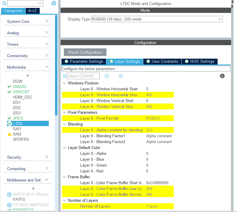
LTDC 구성
- NVIC 설정
LTDC global interrupt와LTDC global error interrupt모두 사용하지 않으므로 비활성화해야 합니다.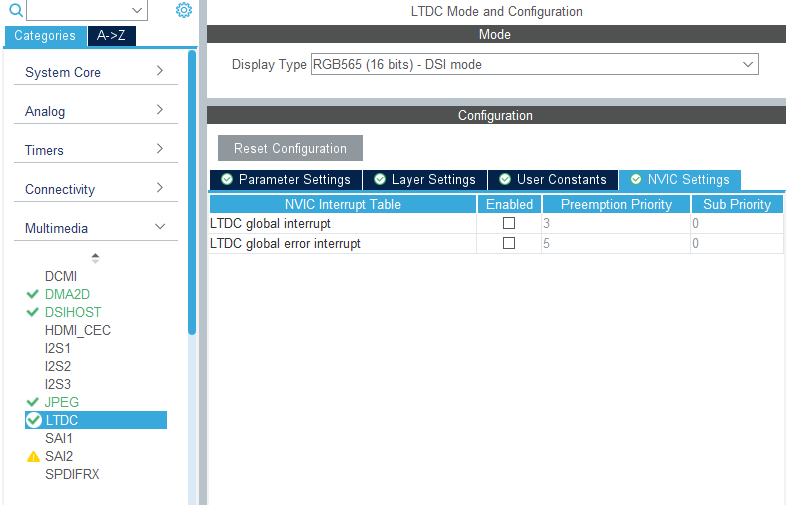
LTDC NVIC 설정
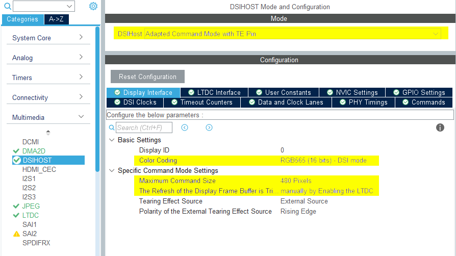
DSIHOST 구성
- 모드
DSIHost를 _*Adapted Command Mode with TE Pin**으로 설정
- 디스플레이 인터페이스
Color Coding을 RGB565 (16 bits) - DSI mode로 설정Maximum Command Size를 디스플레이 폭에 맞는 숫자로 설정The Refresh of the Display Frame Buffer is Triggered를 manually by Enabling the LTDC로 설정- 나머지 구성은 선택한 LCD HW에 따라 다릅니다
DSIHOST 구성
- NVIC 설정
DSI global interrupt활성화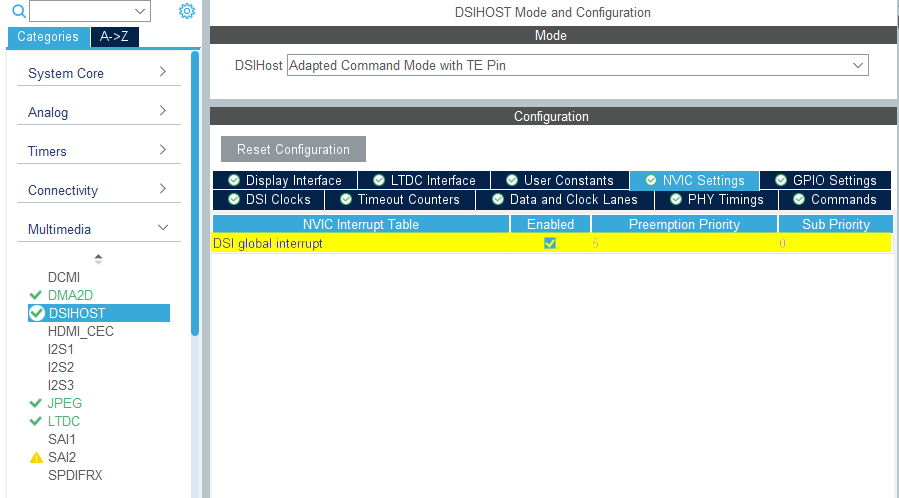
DSIHOST NVIC 설정
TouchGFX Generator
- 모드
- Graphics Application 활성화
- TouchGFX Generator
Display / Interface를 Parallel RGB (LTDC)로 설정(여전히 애플리케이션이 통신해야 하는 컨트롤러이기 때문)Application Tick Source를 Custom으로 설정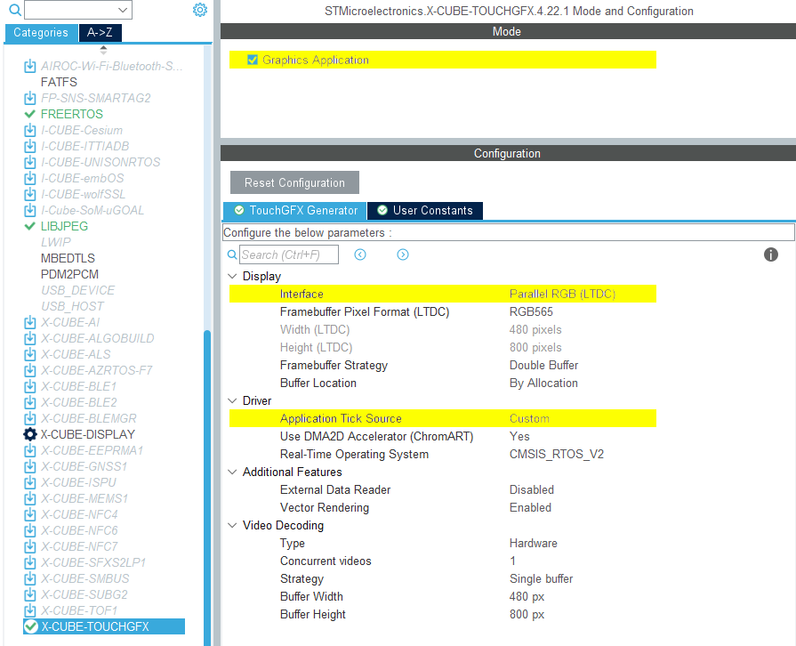
TouchGFX Generator 구성
사용자 코드
TouchGFX Generator는 DSI Host 컨트롤러를 통해 프레임버퍼 메모리에서 디스플레이로 픽셀을 전송하고 디스플레이를 TouchGFX 엔진과 동기화할 수 있도록 LTDC를 구성하는 부분 TouchGFX AL만 생성할 수 있습니다. 하지만 이를 달성하는 데 필요한 모든 핸들은 TouchGFX Generator에 의해 생성됩니다.
일반적으로 임베디드 GRAM이 탑재된 디스플레이의 경우 TouchGFXHAL.cpp에서 생성된 TouchGFX HAL 핸들을 구현하려면 다음 단계를 수행해 픽셀을 디스플레이로 전송하고 디스플레이를 TouchGFX Engine과 동기화해야 합니다:
- "VSYNC"(TE(Tearing Effect) 신호라고도 불림)가 TouchGFX Engine에 신호를 보낼 때까지 대기합니다.
- 다시 그려질 프레임 버퍼의 영역을 기준으로 "디스플레이 커서"와 "활성 창"(업데이트되는 디스플레이의 영역)을 이 영역과 일치하는 GRAM의 위치로 이동시킵니다.
- GRAM에 입력되는 픽셀 데이터를 기록할 준비를 합니다. 사용되는 프레임 버퍼 전략과 디스플레이 인터페이스에 따라 이는 프레임 버퍼 포인터를 바꾸거나, TouchGFX Engine에 신호를 보내거나, 이전 전송이 완료될 때까지 기다릴 수도 있습니다.
- 픽셀 데이터를 전송합니다.
어떤 디스플레이를 사용하고 프레임 버퍼 전략이 무엇인지에 따라 위 단계의 구현이 달라질 수 있습니다.
특히 DSI 명령 모드 인터페이스에 필요할 수 있는 몇 가지 조정에 대해서는 아래에 설명되어 있습니다.
DSIHOST / LTDC 초기화 시퀀스
MX_DSIHOST_DSI_Init()에 대한 호출은 MX_LTDC_Init()보다 먼저 수행되어야 합니다. 이 호출은 STM32CubeMX에서 처리해야 합니다. 이것이 올바르지 않다면 사용자 코드 섹션에서 순서를 수정하세요.
HAL_DSI_Start()를 호출한 후, DSIHOST 클럭을 DSIPHY 소스로 전환합니다:
static void MX_DSIHOST_DSI_Init(void)
{
  ...
  /* Switch to DSI PHY PLL clock */
  RCC_PeriphCLKInitTypeDef PeriphClkInit;
  PeriphClkInit.PeriphClockSelection = RCC_PERIPHCLK_DSI;
  PeriphClkInit.DsiClockSelection    = RCC_DSICLKSOURCE_DSIPHY;
  HAL_RCCEx_PeriphCLKConfig(&PeriphClkInit);
  /* USER CODE END DSIHOST_Init 2 */
  ...
}
사용자는 MX_LTDC_Init() 함수의 끝에 사용된 LCD 컨트롤러에 필요한 초기화 코드를 추가해야 합니다. 해당 코드는 DSI HAL API HAL_DSI_ShortWrite() 및 HAL_DSI_LongWrite()를 기반으로 합니다.
  static void MX_LTDC_Init(void)
  {
    ...
    /* USER CODE BEGIN LTDC_Init 2 */
    // Specific LCD controller's initialization code
    ...

    // Exit Sleep Mode
    if (HAL_DSI_ShortWrite(&hdsi, 0, DSI_DCS_SHORT_PKT_WRITE_P0, DSI_EXIT_SLEEP_MODE, 0x00) != HAL_OK)
    {
      Error_Handler();
    }

    HAL_Delay(120);
    /* USER CODE END LTDC_Init 2 */
    ...
  }
DSI 명령 모드에서 TouchGFXHAL 클래스 업데이트
이 애플리케이션의 첫 번째 프레임을 렌더링할 때까지 MIPI DSI 디스플레이가 켜지지 않게 할 수 있는 한 가지 방법은 TouchGFX에서 첫 번째 프레임을 렌더링할 때까지 디스플레이를 꺼진 상태로 유지하도록 TouchGFXHAL::endFrame 함수를 보호하는 것입니다. TouchGFXHAL::endFrame()을 아래와 같이 업데이트해서 PWM 출력용으로 구성된 HW 타이머를 통해 LCD와 그 백라이트를 활성화할 수 있습니다.
void TouchGFXHAL::endFrame()
{
    if (!display_on)
    {
        display_on = true;
        /* Enable the LCD, Send Display on DCS command to display */
        HAL_DSI_ShortWrite(&hdsi, 0, DSI_DCS_SHORT_PKT_WRITE_P1, DSI_SET_DISPLAY_ON, 0x00);
        /* Start PWM Timer channel */
        (void)HAL_TIM_PWM_Start(&htim8, TIM_CHANNEL_2);
        /* Enable Backlight by setting Brightness to 100% */
        __HAL_TIM_SET_COMPARE(&htim8, TIM_CHANNEL_2, 2U * 100);
    }

    TouchGFXGeneratedHAL::endFrame();
}
지원되는 프레임 버퍼 전략
- 단일
- 이중
- 부분 - GRAM 디스플레이
Further reading
DSI 명령 모드는 일반적으로 디스플레이가 픽셀을 스캔하는 것보다 빠른 속도로 픽셀을 GRAM으로 전송할 수 있을 만큼 충분히 높은 대역폭을 보유합니다. 이는 FMC 병렬 디스플레이 인터페이스와 매우 유사합니다. 따라서 DSI 명령 모드에서 작동하는 TouchGFX AL의 구현 단계는 FMC 병렬 디스플레이 인터페이스와 매우 유사합니다.
Further reading
단일
현재 어떤 TouchGFX Board Support에도 DSI 명령 모드를 사용하는 단일 버퍼링에 대한 참조 구현은 없습니다. 설정은 FMC 단일 버퍼 설정과 유사하나 FMC 대신 DSI 명령 모드 드라이버 기능을 사용합니다.
이중
현재 어떤 TouchGFX Board Support에도 DSI 명령 모드를 사용하는 이중 버퍼링에 대한 참조 구현은 없습니다. 설정은 FMC 이중 버퍼 설정과 유사하나 FMC 대신 DSI 명령 모드 드라이버 기능을 사용합니다.
부분 - GRAM 디스플레이
현재 어떤 TouchGFX Board Support에도 DSI 명령 모드를 사용하는 부분 GRAM 디스플레이에 대한 참조 구현은 없습니다. 설정은 FMC 부분 - GRAM 디스플레이 설정과 유사하나 FMC 대신 DSI 명령 모드 드라이버 기능을 사용합니다.