프레임버퍼
프레임버퍼란 그래픽 엔진에서 디스플레이에 표시할 다음 이미지를 준비할 목적으로 업데이트되는 메모리를 말합니다.
프레임버퍼는 일정 크기의 RAM에 인접한 부분입니다.

프레임버퍼 메모리
프레임버퍼에는 연관된 가로와 세로가 있습니다. 이러한 이유로 프레임버퍼는 x,y 좌표로 인덱싱이 가능한 2D 메모리라는 인식이 있습니다.

2D 프레임버퍼 메모리
프레임버퍼에는 연관된 색상 형식이 있습니다. 프레임버퍼의 시작 부분은 이러한 색상 형식에 따른 색상을 나타냅니다. 따라서 프레임버퍼의 이러한 각 시작 부분을 픽셀이라고 칭하겠습니다.
프레임버퍼의 픽셀 메모리 주소를 계산하여 저장된 색상을 업데이트하면 프레임버퍼에서 x, y 위치의 픽셀 색상을 업데이트할 수 있습니다.
uint32_t pixelAddress = x + y * WIDTH;
framebuffer[ pixelAddress ] = newColor;
마찬가지로 프레임버퍼의 픽셀 색상을 가져와서 계산에 사용할 수도 있습니다. 예를 들어 프레임버퍼의 픽셀 색상을 어둡게 할 수 있습니다(darken 함수를 사용할 수 있는 경우).
uint32_t pixelAddress = x + y * WIDTH;
framebuffer[ pixelAddress ] = darken( framebuffer[ pixelAddress ] );
프레임버퍼 메모리는 위와 같이 픽셀 단위로 쓰거나 읽는 경우가 많지 않고, Chrom-ART DMA와 같은 시스템 기반 하드웨어 기능을 주로 이용해 쓰거나 읽습니다.
색상
TouchGFX에서 프레임버퍼의 픽셀 색상 형식은 다음 중 한 가지입니다.
- 그레이스케일 1, 2 또는 4bpp(Bits per Pixel) 그레이스케일
- 하이 또는 트루 컬러 16, 24 또는 32bpp 색상
bpp를 많이 사용할수록 프레임버퍼에서 나타낼 수 있는 고유 색상도 늘어납니다. 나아가, bpp를 많이 사용할수록 프레임버퍼의 메모리 소비량도 증가합니다.
디스플레이
프레임버퍼의 내용은 최종적으로 물리적 디스플레이에 전송되어 표시됩니다. 따라서 프레임버퍼와 디스플레이의 픽셀 가로 및 세로가 서로 동일한 경우가 많습니다.

24bpp 프레임버퍼 내용과 그에 따른 디스플레이 결과
Further reading
프레임버퍼 위치
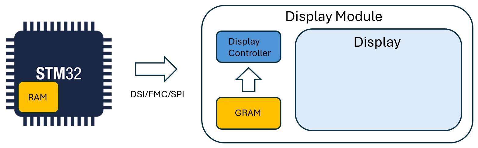
마이크로컨트롤러 기반의 그래픽 시스템을 크게 단순화하면 다음과 같습니다.
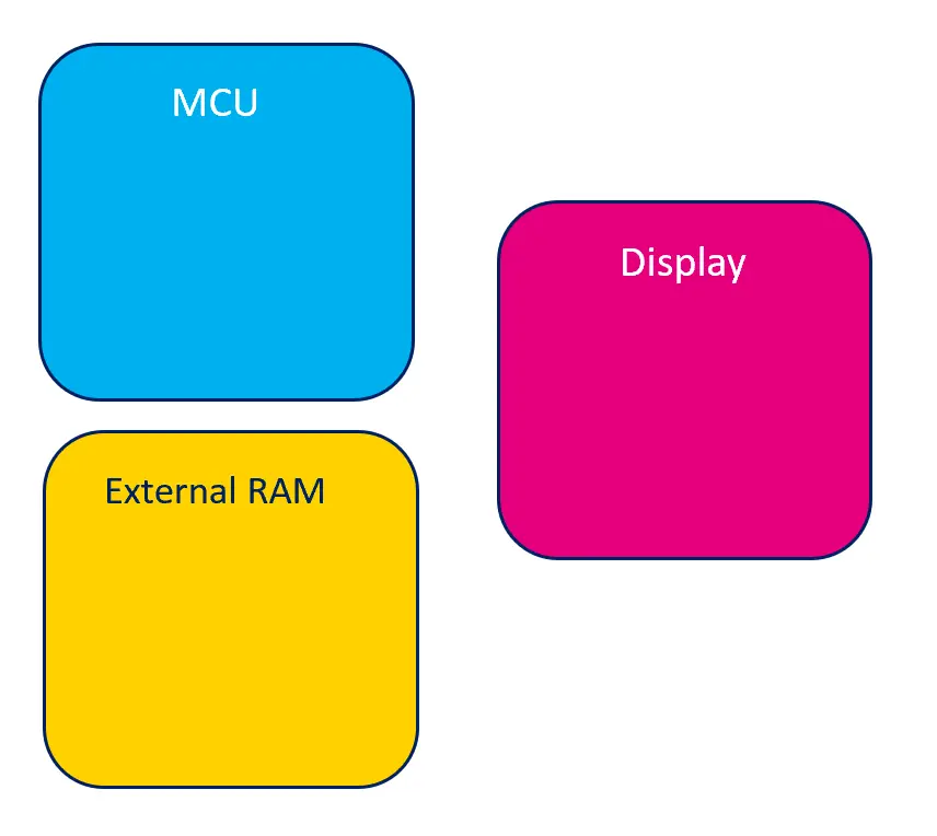
그래픽 시스템 개략도
프레임버퍼는 MCU 내부 또는 외부 RAM에 저장됩니다.
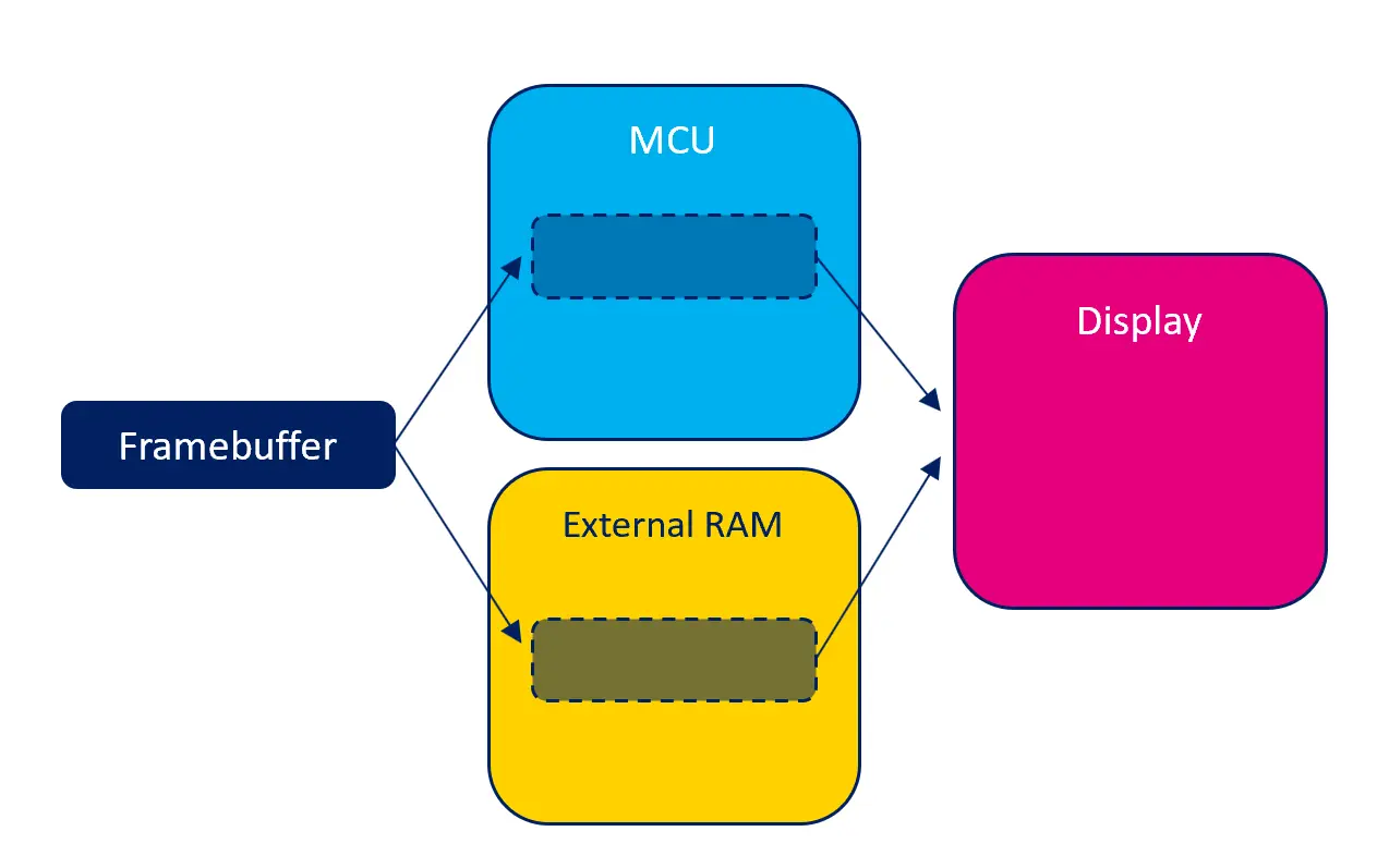
가능한 프레임버퍼 위치
각 위치는 잠재적 장점과 단점이 있습니다.
내부 RAM
프레임버퍼를 MCU 내부 RAM에 저장하면 프레임버퍼에 대한 읽기/쓰기 액세스 속도를 극대화할 수 있습니다. 따라서 TouchGFX 애플리케이션도 최대한 원활하게 실행됩니다. 반대로 내부 RAM은 다수의 시스템 구성요소에서 사용하여 매우 부족한 리소스이기 때문에 프레임버퍼가 많은 용량을 차지하기는 어려울 수 있습니다.
하지만 만약 가능하다면 프레임버퍼를 내부 RAM에 저장하여 RAM을 추가할 필요가 없기 때문에 시스템의 전반적인 비용을 줄일 수 있습니다.
외부 RAM
시스템에 외부 RAM이 있다면 프레임버퍼를 외부 RAM에 저장하여 내부 RAM을 대체할 수도 있습니다. 외부 RAM에 대한 읽기/쓰기 액세스 속도는 내부 RAM에 비해 대체로 느린 반면, 외부 RAM의 용량은 일반적으로 내부 RAM보다 훨씬 큽니다 따라서 외부 RAM이 유일한 해결책일 때도 있습니다.
MCU는 캐싱과 같이 외부 RAM에 대한 액세스 속도를 높여주는 기능을 지원하기도 합니다. 자세한 내용은 MCU 섹션을 참조하십시오.
GRAM이 탑재된 디스플레이
시스템의 디스플레이 유형에 따라 디스플레이에 메모리가 내장되어 있을 수 있습니다(종종 GRAM이라 칭함). 이러한 메모리에는 디스플레이의 “물리적” 픽셀 내용이 저장됩니다. 픽셀 메모리가 디스플레이에 내장된다는 것은 디스플레이가 작동 중일 때도 MCU가 유휴 상태가 될 수 있다는 것을 의미합니다.
TouchGFX 프레임버퍼는 디스플레이의 RAM에 저장되지 않는데, 그 이유는 디스플레이의 내부 메모리가 메모리 매핑이 되지 않으며 랜덤 픽셀 읽기 또는 쓰기에 적합하지 않기 때문입니다. 대신에 TouchGFX는 프레임버퍼를 내부 또는 외부 RAM에 저장해두고 필요할 때 이를 디스플레이 RAM으로 전송합니다.
메모리 사용
프레임버퍼의 메모리 소비량은 색상 크기와 픽셀 수에 따라 달라집니다.
일반적으로 프레임버퍼에서 사용되는 메모리의 크기는 가로 세로 색 심도(비트) / 8바이트로 계산합니다.
| 해상도(픽셀) | 색상(bpp) | 계산 | 메모리 사용량(바이트) |
|---|---|---|---|
| 800 x 480 | 16bpp | 800 480 16 / 8 | 768,000B |
| 480 x 272 | 24bpp | 480 272 24 / 8 | 391,680B |
| 100 x 100 | 8bpp | 100 100 8 / 8 | 10,000B |
프레임버퍼가 다수일 경우에는 사용되는 메모리의 크기도 그만큼 커집니다. 예를 들어 프레임버퍼를 2개 사용하는 이중 버퍼링 기법을 적용하면 사용되는 메모리 크기도 2배로 늘어납니다.
반대로 프레임버퍼를 1개 미만으로 사용하는 경우에는 애플리케이션에서 메모리 크기를 명시적으로 할당하고 제어합니다. 따라서 메모리 사용량을 전적으로 맞춤 설정할 수 있지만 너무 적게 사용하면 그래픽의 전반적인 성능이 느려질 수 있습니다.
프레임버퍼 전략
프레임버퍼 전략은 TouchGFX 렌더링과 기존 하드웨어(MCU, RAM, 디스플레이) 간에 가장 적합한 조합을 구성하게 해주는 핵심 기능입니다. 새 하드웨어를 선택할 경우 사용 사례와 관련해 사용 가능한 프레임버퍼 전략을 익히는 것이 좋습니다. 올바르게 선택한다면 프레임버퍼를 위한 RAM의 양과 적합한 디스플레이 인터페이스 측면에서 최소 요구 하드웨어를 선택할 수 있으므로 하드웨어 비용을 최적화하는 데 도움이 됩니다.
프레임버퍼 전략은 프레임버퍼에 사용될 RAM의 양을 정의하고 TouchGFX가 RAM에 렌더링 되는 방식을 제어합니다. 전략은 시스템의 이용 가능한 RAM 및 디스플레이 유형과 일치해야 합니다. TouchGFX는 GRAM이 탑재되거나 탑재되지 않은 디스플레이 시스템에 적용 가능한 3가지의 전략을 제공합니다. 다음은 전략에 대한 개요로, 디스플레이 시스템과 관련된 장단점을 강조하여 설명합니다.
GRAM이 탑재되지 않은 디스플레이
| 전략 | 장점 | 단점 | 사용 사례 |
|---|---|---|---|
| 이중 | 깨짐의 위험이 없고 최적의 렌더링 시간 제공 | 프레임버퍼 2개를 위한 RAM 필요 | 고성능 UI |
| 단일 | 1개의 프레임 버퍼를 위한 RAM만 필요 | 깨짐의 위험이 있고 차선의 렌더링 시간 제공 | 높음-중간 성능의 UI |
| 부분 | 1개 미만의 프레임버퍼를 위한 RAM만 필요 | 깨짐의 위험이 크고 CPU 부하가 큼 | 중간-낮은 성능의 UI |
GRAM이 탑재된 디스플레이
| 전략 | 장점 | 단점 | 사용 사례 |
|---|---|---|---|
| 이중 | 깨짐의 위험이 없고 최적의 렌더링 시간 제공 | 프레임버퍼 2개를 위한 RAM 필요 | 고성능 UI |
| 단일 | 1개의 프레임버퍼를 위한 RAM만 필요, 깨짐 위험 없음 | 최적이 아닌 렌더링 시간 | 높음-중간 성능의 UI |
| 부분 | 1개 미만의 프레임버퍼를 위한 RAM만 필요 | 깨짐 위험 | 중간-낮은 성능의 UI |
깨짐 현상
깨짐 현상(Tearing)은 두 프레임의 픽셀 데이터가 하나의 스크린에 표시될 때 디스플레이에 나타나는 시각적 아티팩트로, 스크린의 절반에는 기존 프레임이, 나머지 절반에 현재 프레임이 표시되면서 가로로 명확한 분할선(깨짐)이 보이는 것을 말합니다. 깨짐의 위치는 타이밍에 따라 다양하며 보통 스크린 이곳저곳에 나타나 주의를 산만하게 만듭니다.
UI 성능
전반적인 성능 문서에서 UI의 성능 측면에 대한 내용을 확인할 수 있으며 여기에는 개별 UI 구성 요소와 그 구조가 성능에 미치는 영향에 대한 내용도 포함됩니다. 프레임버퍼 전략의 매락에서는 다음과 같이 생각해 볼 수 있습니다:
- 높은 성능: 텍스처 매퍼, SVG, 스크린 전환 등의 복잡한 여러 UI 구성 요소/애니메이션을 사용하는 UI
- 중간 성능: 소수의 UI 구성 요소/애니메이션을 사용하는 UI
- 낮은 성능: 복잡하지 않은 UI 구성 요소/애니메이션을 사용하는 UI
Note
용어집
다음 용어는 다양한 프레임버퍼 전략을 설명하는 데 사용됩니다.
- 디스플레이 컨트롤러(DC) - 메모리에서 픽셀을 읽는 하드웨어로, 픽셀이 포함된 메모리를 지속적으로 읽습니다. 경우에 따라 주사선이라 불리기도 합니다.
- 디스플레이 전송(DT) - 프레임버퍼 메모리에서 GRAM으로 픽셀을 전송할 책임이 있는 하드웨어로, 필요한 경우 MCU에 의해서만 시작됩니다. 경우에 따라 전송선이라 불리기도 합니다.
- 프레임버퍼 쓰기(W) - 프레임버퍼에 픽셀을 렌더링 하는 것입니다.
GRAM이 탑재되지 않은 디스플레이
다음은 GRAM이 탑재되지 않은 디스플레이에서 프레임버퍼 전략의 작동 개념을 보여줍니다. 모든 전략에서 공통적으로 나타나는 것은 프레임버퍼에서 계속해서 픽셀 데이터를 읽어오는 디스플레이 컨트롤러를 사용하는 것입니다.
이중 버퍼링 전략
프레임버퍼가 두 개일 경우 디스플레이 컨트롤러가 다른 프레임버퍼를 스캔하는 동안 다음 프레임을 하나의 프레임버퍼로 렌더링 할 수 있습니다. 다음 프레임을 렌더링하는 시간은 디스플레이 컨트롤러에 의해 제한되지 않습니다. 다음 프레임이 준비될 때까지 프레임버퍼 변경은 차단됩니다. 즉, 디스플레이 컨트롤러는 현재 프레임버퍼를 다시 한 번 스캔하기만 하므로 깨짐이 발생할 위험이 없습니다. 디스플레이 컨트롤러가 전체 프레임버퍼를 스캔하고 렌더링이 완료된 후에 프레임버퍼가 변경됩니다.

이중 버퍼링 전략 개념
단일 버퍼링 전략
프레임버퍼가 한 개라면 디스플레이 컨트롤러가 스캔하는 것과 동일한 프레임버퍼로 다음 프레임을 렌더링 할 수 있습니다. 다음 프레임의 렌더링 시간은 디스플레이 컨트롤러에 의해 제한됩니다. 디스플레이 컨트롤러는 지속적으로 스캔하므로, 프레임버퍼에 쓰는 시간이 너무 길어지면, 디스플레이 컨트롤러가 쓰기 영역과 충돌하여(따라잡아) 깨짐 현상이 발생합니다. 이는 복잡한 UI 구성 요소를 렌더링하는 것으로 인해 유발됩니다.
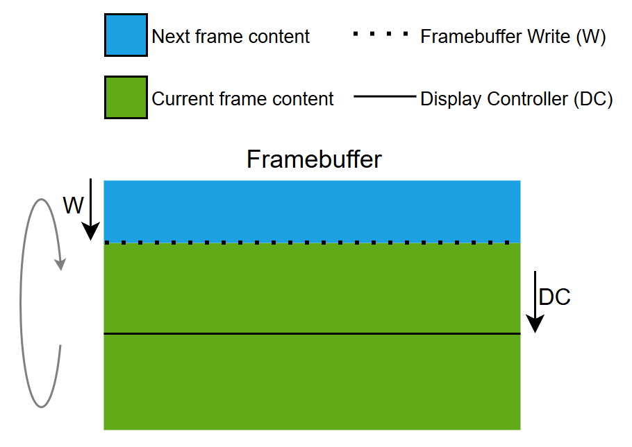
단일 버퍼링 전략 개념
부분 버퍼링 전략
단일 부분 프레임버퍼 블록은 메모리 관리 장치(MMU)를 통해 전체 크기의 프레임버퍼를 에뮬레이션하는 데 사용됩니다. 따라서 이 전략은 에뮬레이션 프레임버퍼 전략으로도 알려져 있습니다.
부분 블록은 디스플레이 컨트롤러의 단계 및 속도에 따라 에뮬레이션된 프레임버퍼를 통해 아래로 이동되는 슬라이딩 창의 역할을 합니다.
부분 프레임버퍼 블록만 있다면, 해당 블록이 현재 프레임을 렌더링 하는 데 여러 차례 재사용되므로 다음 프레임의 일부만 렌더링 할 수 있습니다. 부분 블록이 재사용되면 대량의 소규모 렌더링 작업이 진행되므로 CPU 부하가 커집니다. 다음 프레임의 렌더링 시간은 디스플레이 컨트롤러와 부분 블록의 크기에 의해 제한됩니다. 디스플레이 컨트롤러는 계속해서 스캔하므로, 에뮬레이션 프레임버퍼의 특정 영역에 부분 프레임버퍼 블록을 쓰는 데 너무 긴 시간이 걸리면, 디스플레이 컨트롤러가 쓰기 영역과 해당 쓰기 영역과 충돌하여(따라잡아) 깨짐 현상이 발생합니다. 이는 복잡한 UI 구성 요소를 렌더링하는 것으로 인해 유발됩니다. 디스플레이 컨트롤러와 프레임버퍼 렌더링의 작업 영역이 훨씬 작으므로 단일 버퍼링 전략에 비해 깨짐이 발생할 가능성이 더 높습니다.
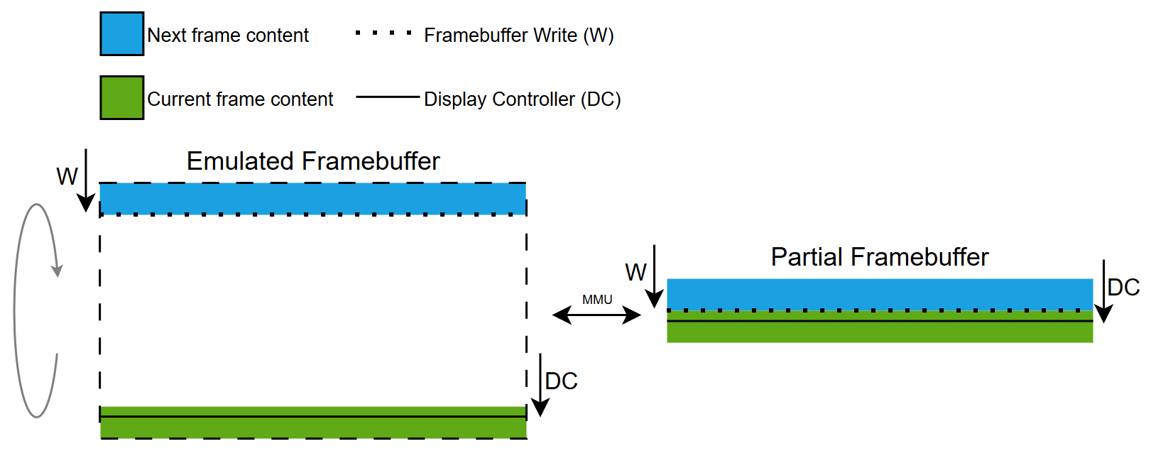
부분 버퍼링 전략 개념
GRAM이 탑재된 디스플레이
다음은 GRAM 디스플레이에서 프레임버퍼 전략의 작동 개념을 보여줍니다. 모든 전략에서 공통적인 점은 프레임버퍼의 픽셀 데이터를 디스플레이의 GRAM으로 전송하기 위해 디스플레이 인터페이스를 사용한다는 점입니다.
이중 버퍼링 전략
프레임버퍼가 두 개일 경우 하나의 프레임버퍼에서 GRAM으로 픽셀이 전송되는 동안 다음 프레임이 다른 프레임버퍼에 렌더링 될 수 있습니다. 다음 프레임의 렌더링 시간은 디스플레이 전송에 의해 제한되지 않습니다. 디스플레이 전송은 다음 프레임이 준비된 경우에만 시작되므로, 디스플레이 컨트롤러가 이미 GRAM에 있는 내용을 스캔하기 때문에 깨짐이 발생할 위험이 없습니다. 디스플레이 전송과 렌더링이 완료된 후에 프레임버퍼가 서로 교체됩니다.
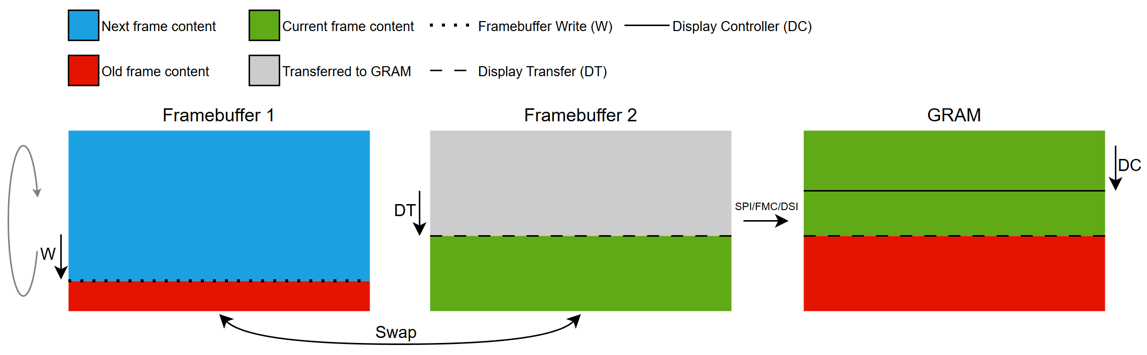
이중 버퍼링 전략 개념
단일 버퍼링 전략
프레임버퍼가 한 개라면 픽셀이 GRAM으로 전송되는 동일한 프레임버퍼로 다음 프레임을 렌더링 할 수 있습니다. 다음 프레임의 렌더링 시간은 디스플레이 전송 대역폭에 의해 제한됩니다. 디스플레이 전송은 다음 프레임이 준비된 경우에만 시작되므로, 디스플레이 컨트롤러가 이미 GRAM에 있는 내용을 스캔하기 때문에 깨짐이 발생할 위험이 없습니다. 업데이트될 해당 영역이 GRAM으로 전송될 때까지는 다음 프레임의 렌더링이 완료될 수 없습니다.
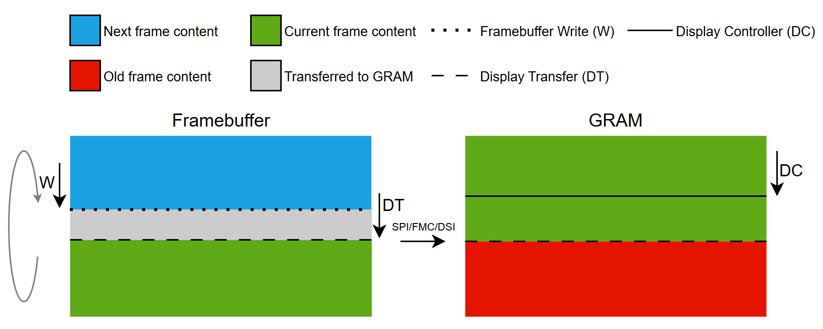
단일 버퍼링 전략 개념
부분 버퍼링 전략
완전한 크기의 프레임버퍼를 에뮬레이션하는 데 하나 이상의 부분 프레임버퍼 블록이 사용됩니다.
현재 프레임에서 업데이트가 필요한 모든 영역을 렌더링 하기 위해 부분 블록이 재사용됩니다. 블록이 렌더링되면 GRAM으로 전송되어 후속 렌더링에 사용될 수 있습니다.
깨짐이 발생할 위험을 최소화하기 위해 디스플레이 전송에 의해 업데이트되는 GRAM과 디스플레이 컨트롤러 주사선 사이에 최대한의 여유 공간을 확보하려 노력합니다. 이는 전송선을 주사선 뒤에 두는 방식으로, 현재 프레임만을 렌더링할 수 있으며 다음 프레임의 렌더링은 시작할 수는 없다는 뜻입니다. 현재 프레임의 렌더링 시간은 정의된 부분 블록의 개수와 각 블록을 전송하는 데 소요되는 시간에 달려 있습니다. 이는 사용 가능한 블록이 있을 경우 디스플레이 컨트롤러 주사선보다 앞에 있는 블록을 렌더링 할 수 있다는 뜻입니다. 현재 프레임의 모든 더티 영역을 렌더링 및 전송하는 데 디스플레이 컨트롤러보다 긴 시간이 소요될 경우 그 주사선이 전송선 주변을 둘러싸고 따라잡아 깨짐이 발생할 수 있습니다. 이는 복잡한 UI 구성 요소를 렌더링 하거나 너무 많은 픽셀을 전송하는 것으로 인해 유발됩니다.
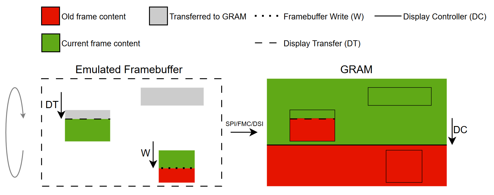
부분 버퍼링 전략 개념
프레임버퍼 전략 시작하기
다음 섹션에서는 일반적인 하드웨어 설정을 소개하고 다양한 하드웨어 설정에서 프레임버퍼 전략을 사용하는 방법에 대한 시나리오를 제시합니다.
Further reading
GRAM이 탑재된 디스플레이
이 디스플레이 유형에는 디스플레이와 동일한 크기의 전용 RAM 버퍼, 즉 전체 크기의 프레임버퍼가 있습니다.
GRAM이 탑재된 디스플레이
이 디스플레이 유형을 위한 인터페이스는 다음과 같습니다:
- FMC
- SPI
- DSI(명령 모드)
이러한 인터페이스의 사용을 보여주는 시나리오는 아래에서 확인할 수 있습니다:
GRAM이 탑재되지 않은 디스플레이
이 디스플레이 유형에는 전용 RAM 버퍼가 없습니다.
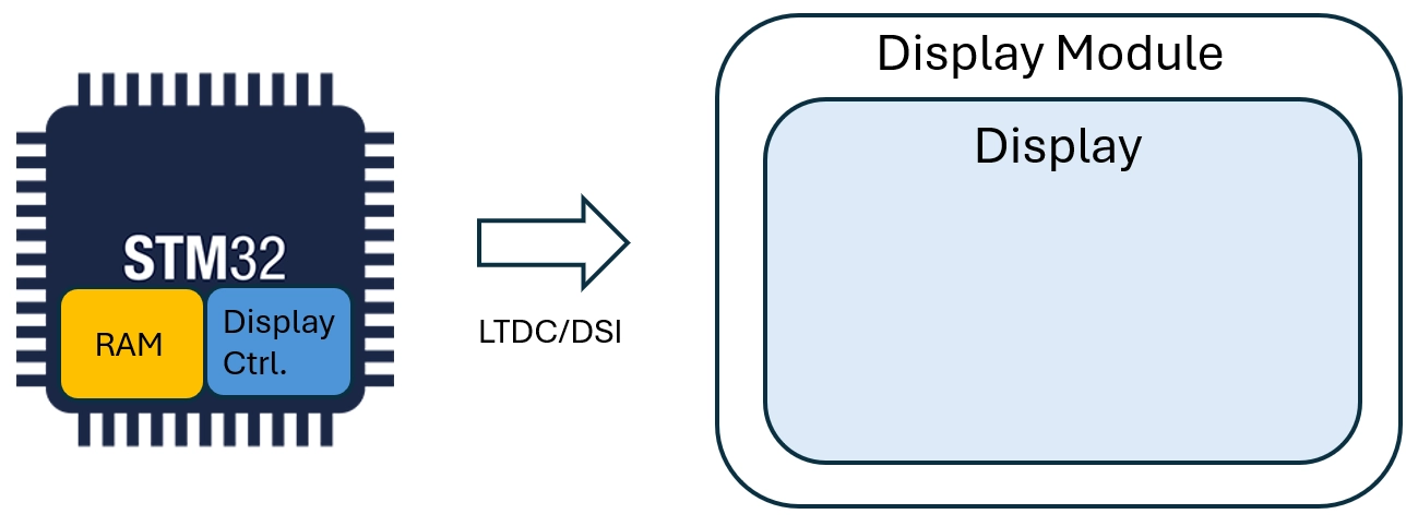
GRAM이 탑재되지 않은 디스플레이
이 디스플레이 유형을 위한 인터페이스는 다음과 같습니다:
- LTDC
- DSI(비디오 모드)
이러한 인터페이스의 사용을 보여주는 시나리오는 아래에서 확인할 수 있습니다: