MIPI-DSI命令模式
本场景描述在使用配备显示串行接口 (DSI) 和GRAM的显示屏时,如何在命令模式下配置MIPI DSI接口以及配置TouchGFX Generator。 本文使用的示例采用16位RGB565帧缓存格式,并在STM32CubeMX中进行配置。
Note
配置
LTDC 配置
- 模式
- 将
显示类型设置为RGB565(16位)-DSI模式
- 将
- 层设置
- 将
层数设置为1层 - 在
窗口位置和帧缓冲区行长度以及帧缓冲区行数中设置屏幕分辨率 - 设置
0层-像素格式设置为RGB565 - 设置
0层- Alpha混合常数为255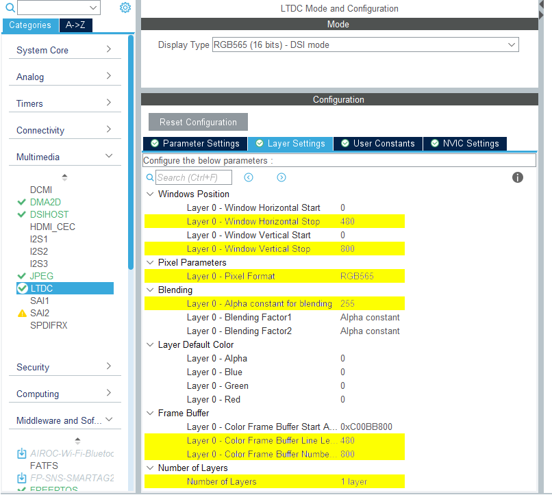
LTDC 配置
- 将
- NVIC 设置
LTDC全局中断和LTDC全局错误中断均不需要,应禁用。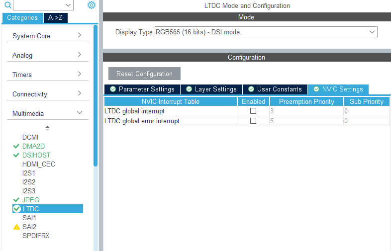
LTDC NVIC 设置
DSIHOST 配置
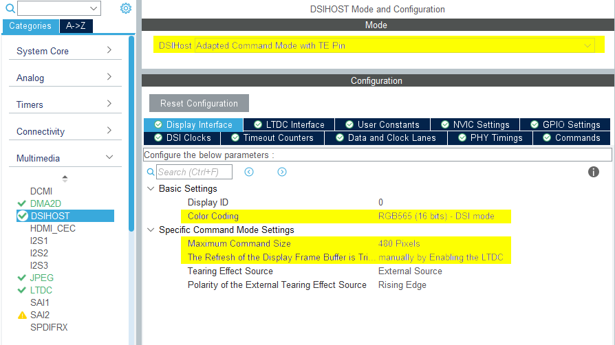
- 模式
- 使用TE Pin将
DSIHost设置为_*自适应命令模式**
- 使用TE Pin将
- 显示接口
- 将
色彩格式设置为“RGB888(16位)- DSI模式” - 根据显示宽度设置
Maximum Command Size - 通过启用LTDC将显示帧缓冲区的
刷新设置为手动触发 - 其余配置取决于所选的LCD HW
DSIHOST 配置
- 将
- NVIC 设置
- 启用
DSI全局中断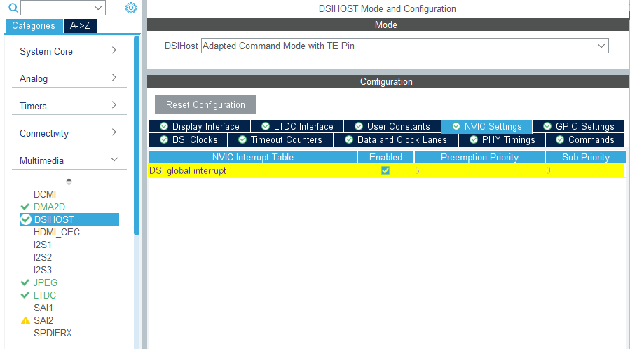
DSIHOST NVIC 设置
- 启用
TouchGFX Generator
- 模式
- 启用图形应用程序
- TouchGFX Generator
- 将
显示/接口设置为并行RGB(LTDC),因为这仍是应用程序与之通信的控制器。 - 将
应用计时源设置为自定义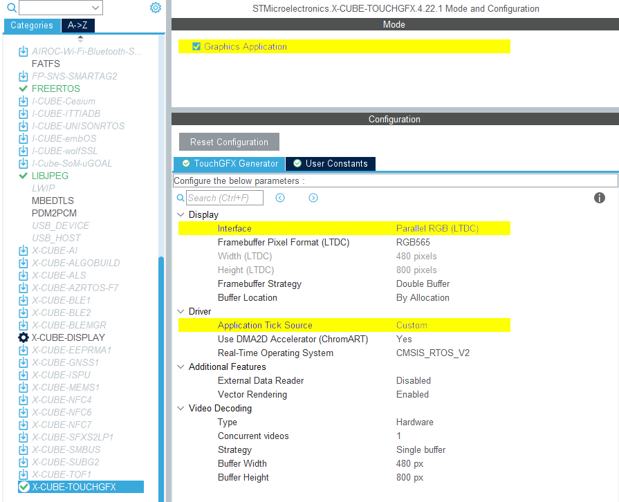
TouchGFX Generator配置
- 将
用户代码
TouchGFX Generator只能生成部分TouchGFX AL,用于配置LTDC以使其通过DSI主机控制器从帧缓存存储器向显示屏传输像素,并使显示屏与TouchGFX引擎同步。 但实现此功能所需的所有句柄均由TouchGFX Generator生成。
对于配备嵌入式GRAM的显示屏,在TouchGFXHAL.cpp中实现生成的TouchGFX HAL句柄时,应执行以下步骤,以便将像素传输到显示屏并使显示屏与TouchGFX引擎同步:
- 等待“VSYNC”(有时也称为“撕裂效应 (TE) 信号”)向TouchGFX引擎发送信号。
- 根据要重绘的帧缓存,将“显示光标”和“活动窗口”(显示屏上正在更新的区域)移动到GRAM中与此区域对应的位置。
- 准备将传入的像素数据写入GRAM。 根据所使用的帧缓存策略和显示接口,这可能需要交换帧缓存指针、向TouchGFX Engine发送信号,或等待之前的传输完成。
- 发送像素数据。
根据所使用的显示屏和帧缓存策略,上述步骤的实现方式会有所不同。
下文介绍了DSI命令模式接口可能特别需要进行的调整。
DSIHOST / LTDC初始化顺序
对MX_DSIHOST_DSI_Init()的调用必须在MX_LTDC_Init()之前完成。 这应由STM32CubeMX处理。 如果不正确,需在用户代码部分修正顺序。
在调用HAL_DSI_Start() 之后,将DSIHOST时钟切换到DSIPHY源。
static void MX_DSIHOST_DSI_Init(void)
{
  ...
  /* 切换到DSI PHY PLL时钟 */
  RCC_PeriphCLKInitTypeDef PeriphClkInit;
  PeriphClkInit.PeriphClockSelection = RCC_PERIPHCLK_DSI;
  PeriphClkInit.DsiClockSelection    = RCC_DSICLKSOURCE_DSIPHY;
  HAL_RCCEx_PeriphCLKConfig(&PeriphClkInit);
  /* 用户编码结束DSIHOST_Init 2 */
  ...
}
用户必须在MX_LTDC_Init() 函数的末尾添加特定于所用LCD控制器的必要初始化代码。 该代码将基于DSI HAL API HAL_DSI_ShortWrite() 和HAL_DSI_LongWrite():
  static void MX_LTDC_Init(void)
  {
    ...
    /* 用户编码开始 LTDC_Init 2 */
    // 特定 LCD 控制器的初始化代码
    ...

    // 退出睡眠模式
    if (HAL_DSI_ShortWrite(&hdsi, 0, DSI_DCS_SHORT_PKT_WRITE_P0, DSI_EXIT_SLEEP_MODE, 0x00) != HAL_OK)
    {
      Error_Handler();
    }

    HAL_Delay(120);
    /* 用户代码结束LTDC_Init 2 */
    ...
  }
更新了DSI命令模式的TouchGFXHAL类
防止MIPI DSI显示在应用程序中的第一帧被渲染之前打开的一种方法是保护TouchGFXHAL::endFrame功能,保持显示关闭,直至TouchGFX渲染第一帧为止。 TouchGFXHAL::endFrame()可像下面这样更新,通过配置为PWM输出的HW定时器启用LCD及其背光。
void TouchGFXHAL::endFrame()
{
    if (!display_on)
    {
        display_on = true;
        /* 开启LCD,向显示器发送Display on DCS命令 */
        HAL_DSI_ShortWrite(&hdsi, 0, DSI_DCS_SHORT_PKT_WRITE_P1, DSI_SET_DISPLAY_ON, 0x00);
        /* 启动PWM定时器通道 */
        (void)HAL_TIM_PWM_Start(&htim8, TIM_CHANNEL_2);
        /* 通过将亮度设置为100%来开启背光 */
        __HAL_TIM_SET_COMPARE(&htim8, TIM_CHANNEL_2, 2U * 100);
    }

    TouchGFXGeneratedHAL::endFrame();
}
支持的帧缓存策略
- 单帧缓存
- 双帧缓存
- 部分缓存 - GRAM显示
Further reading
DSI命令模式通常具备足够高的带宽,将像素传输到GRAM的速度比显示屏扫描像素更快。 这与 FMC并行显示接口非常相似。 因此,对于可在DSI命令模式下正常运行的TouchGFX AL,其实现步骤与FMC并行显示接口非常相似。
Further reading
单帧缓存
目前,TouchGFX板支持没有DSI命令模式单缓冲的参考实现。 设置类似于FMC单缓冲设置,但 使用DSI命令模式驱动程序功能而非FMC。
双帧缓存
目前,TouchGFX板支持没有DSI命令模式双缓冲的参考实现。 设置类似于FMC双缓冲设置,但 使用DSI命令模式驱动程序功能而非FMC。
部分缓存 - GRAM显示
目前,TouchGFX板支持没有DSI命令模式部分 - GRAM显示的参考实现。 设置类似于FMC部分缓存 - GRAM显示设置,但 使用DSI命令模式驱动程序功能而非FMC。