MIPI-DSI指令模式
本情境說明如何在使用具有顯示器序列介面 (DSI) 和 GRAM 的顯示器時,設定指令模式下的 MIPI DSI 介面以及 TouchGFX Generator。 本文使用的範例適用於 16 位元 RGB565 影像緩衝區格式,並介紹 STM32CubeMX 中的設定。
Note
設定
LTDC設定
- 模式
- 將
Display Type(顯示類型)設定為RGB565 (16 bits) - DSI Mode (RGB565 (16位元) - DSI模式)
- 將
- 層設定
- 將
Number of layers(層數)設定為1 layer (1層) - 在
Windows Position(視窗位置)、Frame Buffer Line Length(影像緩衝區行長度)及Frame Buffer Number of Lines(影像緩衝區行數)設定螢幕解析度 - 將
Layer 0 - Pixel Format(第0層 - 像素格式)設定為RGB565 - 將
Layer 0 - Alpha constant for blending(第0層 - 用於混合的Alpha常數)設定為255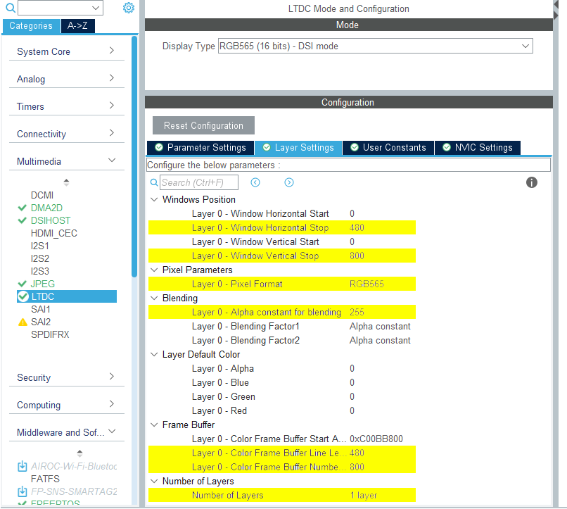
LTDC設定
- 將
- NVIC設定
LTDC global interrupt(LTDC全域中斷)及LTDC global error interrupt(LTDC全域錯誤中斷)都不需要且應停用。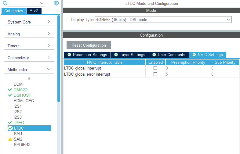
LTDC NVIC設定
DSIHOST設定
- 模式
- 將
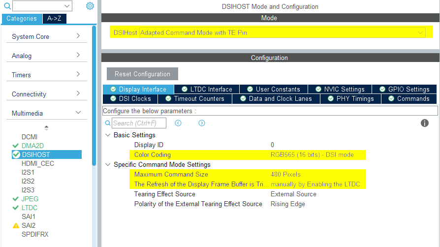
DSIHost設定為_*Adapted Command Mode with TE Pin**(適性指令模式搭配TE腳位)
- 將
- 顯示介面
- 將
Color Coding(色彩編碼)設定為RGB565 (16 bits) - DSI mode (RGB565 (16位元) - DSI模式) - 將
Maximum Command Size(最大指令大小)設定為顯示寬度順序的數字 - 將
The Refresh of the Display Frame Buffer is Triggered(觸發顯示影像緩衝區的刷新頻率)設定為manually by Enabling the LTDC (啟用LTDC手動進行) - 剩餘設定需視選取的LCD硬體而定
DSIHOST設定
- 將
- NVIC設定
- 啟用
DSI global interrupt(DSI全域中斷)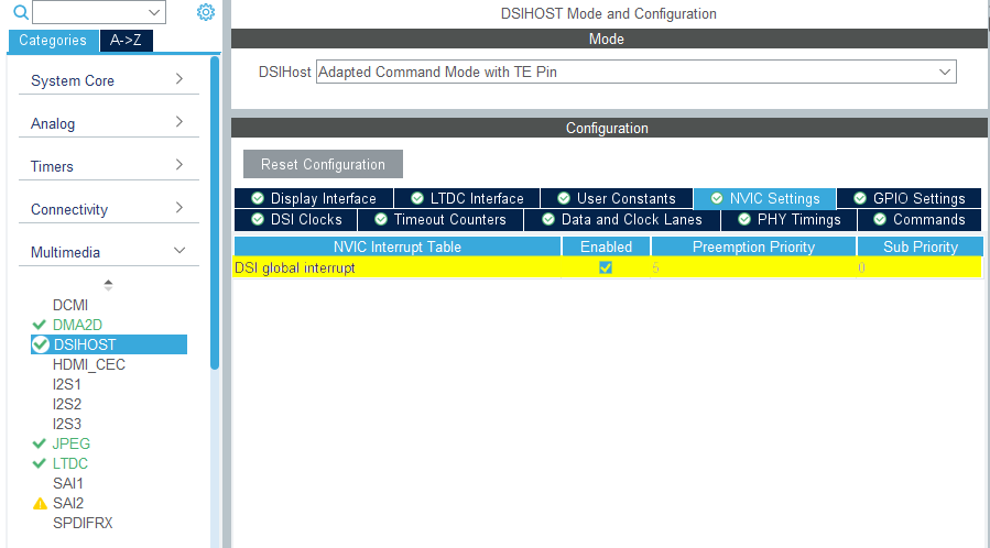
DSIHOST NVIC設定
- 啟用
TouchGFX Generator
- 模式
- 啟用Graphics Application (圖形應用程式)
- TouchGFX Generator
- 將
Display / Interface(顯示/介面)設定為Parallel RGB (LTDC)(平行RGB (LTDC)),因為這仍是應用程式需要通訊的控制器。 - 將
Application Tick Source(應用時標源)設定為Custom (客製)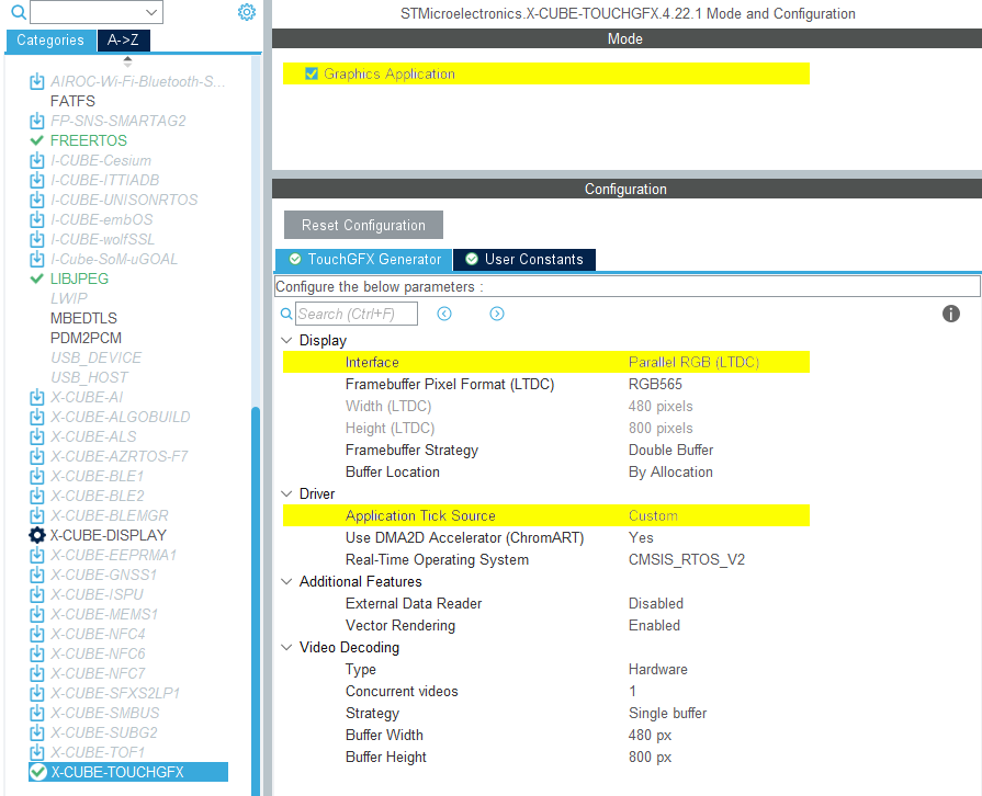
TouchGFX Generator設定
- 將
使用者程式碼
TouchGFX Generator 只能產生局部 TouchGFX AL,其設定 LTDC 透過 DSI 主機控制器將像素從影格緩衝記憶體傳輸到顯示器,並將顯示器與 TouchGFX Engine 同步。 然而,實現此目的所需的所有控制指標均由 TouchGFX Generator 產生。
一般而言,對於具有嵌入式 GRAM 的顯示器,實作 TouchGFXHAL.cpp 中產生的 TouchGFX HAL 控制指標應執行以下步驟,以將像素傳輸到顯示器並使顯示器與 TouchGFX Engine 同步:
- 等待「VSYNC」(有時稱為螢幕撕裂效果 (TE) 訊號) 向 TouchGFX Engine 發出訊號。
- 根據要重繪的影像緩衝區區域,將「顯示游標」和「作用中視窗」(正在更新的顯示區域) 移至 GRAM 中與該區域相符的位置。
- 準備將傳入的像素資料寫入 GRAM。 根據所使用的影像緩衝區策略和顯示器介面,可能是交換影像緩衝區指標、向 TouchGFX Engine 發出訊號,或等待之前的傳輸完成。
- 傳送像素資料。
根據所使用的顯示器和影像緩衝區策略,上述步驟的實作會有所不同。
以下介紹 DSI 指令模式介面可能特別需要的一些調整。
DSIHOST / LTDC初始化順序
對MX_DSIHOST_DSI_Init()的呼叫必須在MX_LTDC_Init()之前完成, 這應該由 STM32CubeMX 處理。 如果不正確,請注意在使用者程式碼區段中修正順序。
呼叫 HAL_DSI_Start() 後,切換 DSIHOST 時脈至 DSIPHY 來源:
static void MX_DSIHOST_DSI_Init(void)
{
  ...
  /* 切換至 DSI PHY PLL 時鐘 */
  RCC_PeriphCLKInitTypeDef PeriphClkInit;
  PeriphClkInit.PeriphClockSelection = RCC_PERIPHCLK_DSI;
  PeriphClkInit.DsiClockSelection    = RCC_DSICLKSOURCE_DSIPHY;
  HAL_RCCEx_PeriphCLKConfig(&PeriphClkInit);
  /* USER CODE END DSIHOST_Init 2 */
  ...
}
使用者必須在 MX_LTDC_Init() function 函數末尾加入所使用的 LCD 控制器所需的初始化程式碼。 該程式碼將基於 DSI HAL APIs HAL_DSI_ShortWrite() 和 HAL_DSI_LongWrite():
  static void MX_LTDC_Init(void)
  {
    ...
    /* USER CODE BEGIN LTDC_Init 2 */
    // 特定 LCD 控制器的初始化程式碼
    ...

    // 退出睡眠模式
    if (HAL_DSI_ShortWrite(&hdsi, 0, DSI_DCS_SHORT_PKT_WRITE_P0, DSI_EXIT_SLEEP_MODE, 0x00) != HAL_OK)
    {
      Error_Handler();
    }

    HAL_Delay(120);
    /* USER CODE END LTDC_Init 2 */
    ...
  }
已更新DSI指令模式的TouchGFXHAL類別
防止MIPI DSI顯示在應用程式中渲染第一幀之前開啟的一種方法是保護TouchGFXHAL::endFrame函數,以便在TouchGFX渲染第一幀之前關閉顯示。 TouchGFXHAL::endFrame()可像下面這樣更新,透過設定為PWM輸出的HW計時器啟用LCD及其背光。
void TouchGFXHAL::endFrame()
{
    if (!display_on)
    {
        display_on = true;
        /* Enable the LCD, Send Display on DCS command to display */
        HAL_DSI_ShortWrite(&hdsi, 0, DSI_DCS_SHORT_PKT_WRITE_P1, DSI_SET_DISPLAY_ON, 0x00);
        /* Start PWM Timer channel */
        (void)HAL_TIM_PWM_Start(&htim8, TIM_CHANNEL_2);
        /* Enable Backlight by setting Brightness to 100% */
        __HAL_TIM_SET_COMPARE(&htim8, TIM_CHANNEL_2, 2U * 100);
    }

    TouchGFXGeneratedHAL::endFrame();
}
支援的影像緩衝區策略
- 單一
- 雙重
- 局部-GRAM 顯示器
Further reading
DSI 指令模式通常具有足夠高的頻寬,將像素傳輸到 GRAM 的速度比顯示器掃描像素的速度快。 這非常類似於 FMC 平行顯示器介面。 因此,DSI 指令模式的 TouchGFX AL 實作步驟與 FMC 平行顯示器介面非常相似。
Further reading
單一
目前,未有 TouchGFX 開發板支援針對 DSI 指令模式的單一緩衝提供參考實作。 其設定類似於 FMC 單一緩衝區設定, 但使用 DSI 指令模式驅動程式函數而不是 FMC。
雙重
目前,未有 TouchGFX 開發板支援針對 DSI 指令模式的雙重緩衝提供參考實作。 其設定類似於 FMC 雙重緩衝區設定, 但使用 DSI 指令模式驅動程式函數而不是 FMC。
局部-GRAM 顯示器
目前,未有 TouchGFX 開發板支援針對 DSI 指令模式的局部-GRAM 顯示器提供參考實作。 其設定類似於 FMC 局部-GRAM 顯示器設定,但使用 DSI 指令模式驅動程式函數而不是 FMC。