LTDC 디스플레이 인터페이스
이 시나리오는 LCD-TFT 병렬 디스플레이 인터페이스를 사용할 때 STM32 LTDC 디스플레이 컨트롤러와 TouchGFX Generator를 구성하는 방법을 설명합니다.
TouchGFX Generator는 프레임 버퍼 메모리에서 디스플레이로 픽셀을 전송하고 디스플레이를 TouchGFX Engine과 동기화할 수 있도록 LTDC를 구성하는 전체 TouchGFX AL을 생성할 수 있습니다.
구성
STM32CubeMX 카테고리 목록의 Multimedia 그룹에서 LTDC를 활성화합니다.
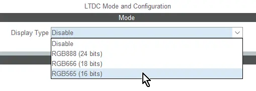
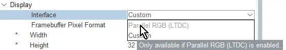
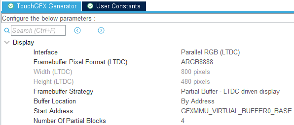
LTDC가 활성화되면 TouchGFX Generator의 Display 섹션을 통해 Parallel RGB(LTDC) 옵션이 활성화됩니다.
STM32CubeMX를 통해 LTDC가 활성화된 후에는 다음 매개변수를 구성해야 합니다:
- 연결된 디스플레이 사양과 일치하도록 LTDC(GPIO 및 타이밍) 구성
- 원하는 TouchGFX 애플리케이션 사양과 일치하도록 LTDC 구성
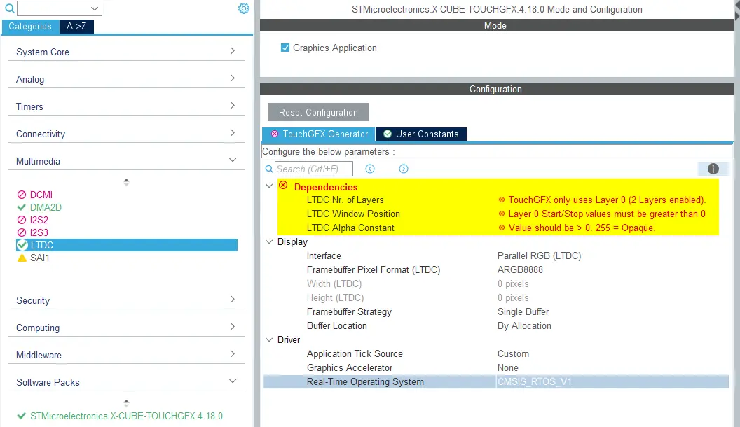
TouchGFX Generator는 STM32CubeMX에서 다양한 구성을 읽어와서 Dependencies 섹션에 경고, 권장 사항 또는 오류 목록을 제공할 수 있습니다. 아래 이미지는 STM32CubeMX에서 처음 LTDC를 활성화할 때 나타나는 종속성 목록을 보여줍니다:
Note
매개변수 및 계층 구성
LTDC 블록에서 다음 매개변수를 구성해야 합니다:
| 종속성 | 설명 |
|---|---|
| 계층 수 | TouchGFX는 단일 계층만 활용할 수 있습니다. |
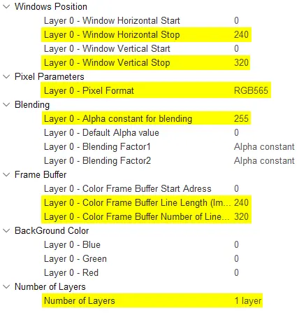
| 창 위치 | 기본적으로 LTDC 계층에서 Horizontal 및 Vertical 창 위치는 각각 0입니다. 창의 Horizontal 및 Vertical 끝 값은 디스플레이 치수와 동일하게 설정해야 합니다. |
| Alpha Constant는 0 | LTDC 계층의 알파 상수(alpha constant)는 0으로 기본 설정되어 있습니다. 애플리케이션에서 항상 전역 알파를 유지할 의도가 아니라면 0 이상으로 설정해야 하고 되도록이면 255로 설정하는 것이 좋습니다. |
아래 그림은 TouchGFX Generator 인터페이스에서 Dependencies 그룹이 사라지는 원인이 될 수 있다는 경고 조건을 충족하는 LTDC 구성을 보여줍니다.
Note
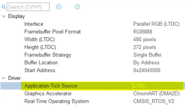
TouchGFX 드라이버/VSYNC 신호
Display Interface로 Parallel RGB(LTDC)가 선택되면 개발자는 TouchGFX Engine 메인 루프 구동에 LTDC 인터럽트를 사용하는 LTDC Application Tick Driver에 액세스할 수 있게 됩니다. 이는 LTDC를 사용할 때 TouchGFX Engine 메인 루프를 구동하는 데 권장되는 방식입니다.
Note
다음 코드는 생성된 LTDC 인터럽트 핸들러로(단일 또는 이중 프레임 버퍼 전략용) 디스플레이가 준비되면 TouchGFX Engine 메인 루프로 자동으로 신호를 보내고 차단을 해제합니다.
TouchGFXGeneratedHAL.cpp
extern "C"
{
    void HAL_LTDC_LineEventCallback(LTDC_HandleTypeDef* hltdc)
    {
        if (!HAL::getInstance())
        {
            return;
        }

        if (LTDC->LIPCR == lcd_int_active_line)
        {
            //entering active area
            HAL_LTDC_ProgramLineEvent(hltdc, lcd_int_porch_line);
            HAL::getInstance()->vSync();
            OSWrappers::signalVSync();

            // Swap frame buffers immediately instead of waiting for the task to be scheduled in.
            // Note: task will also swap when it wakes up, but that operation is guarded and will not have
            // any effect if already swapped.
            HAL::getInstance()->swapFrameBuffers();
            GPIO::set(GPIO::VSYNC_FREQ);
        }
        else
        {
            //exiting active area
            HAL_LTDC_ProgramLineEvent(hltdc, lcd_int_active_line);

            // Signal to the framework that display update has finished.
            HAL::getInstance()->frontPorchEntered();
            GPIO::clear(GPIO::VSYNC_FREQ);
        }
    }
}
LTDC 프레임 버퍼 주소 구성
생성된 TouchGFX HAL은 런타임 시 LTDC 계층 색상 프레임 버퍼 시작 주소를 자동으로 구성하기 때문에 LTDC 구성에서 값을 설정하면 안 됩니다.
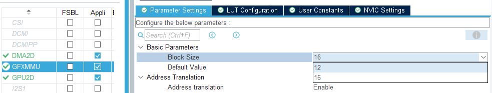
GFXMMU 구성
부분 버퍼 - LTDC 기반 디스플레이 프레임 버퍼 전략을 사용할 경우 GFXMMU가 활성화 및 구성되어 있어야 합니다. GFXMMU는 LTDC에서 읽어온 프레임 버퍼 주소를 물리적 메모리의 부분 프레임 버퍼 블록의 주소로 매핑하는 데 사용됩니다.
우선 Multimedia 섹션의 STM32CubeMX에서 GFXMMU를 활성화하고 주소 번역을 활성화합니다. 16비트 및 32비트 프레임 버퍼 픽셀 형식의 경우 16바이트의 블록 크기가 권장됩니다. 24비트 프레임 버퍼 픽셀 형식의 경우 12바이트의 블록 크기가 필요합니다.
Note
Caution
TouchGFX Generator는 GFXMMU 구성과 LTDC 계층 설정을 토대로 주소를 매핑하는 주소 조회 테이블(LUT)을 자동으로 생성합니다.
GFXMMU를 활성화하고 나면 사용된 부분 블록의 수(또는 부분 프레임 버퍼 블록이 디스플레이에 들어간 횟수)를 TouchGFX Generator에서 구성할 수 있습니다.
이 매개변수는 프레임 버퍼 블록에 사용되는 RAM의 양에 직접적으로 영향을 미칩니다. 블록의 수는 2의 배수여야 하며(예: 2, 4, 8) 따라서 프레임 버퍼 블록은 각각 전체 디스플레이 크기의 1/2, 1/4, 1/8를 차지합니다.
프레임 버퍼 할당
부분 버퍼 - LTDC 기반 디스플레이 프레임 버퍼 전략을 사용할 경우 프레임 버퍼 할당 전략의 의미가 평소와 다릅니다.
By Allocation을 선택하면 TouchGFX Engine은 물리적 부분 프레임 버퍼 블록에 바로 그려지며 LTDC는 GFXMMU 주소 LUT를 읽습니다.
By Address를 선택하면 GFXMMU 가상 버퍼 중 하나의 주소만 지정할 수 있으며 TouchGFX Engine은 렌더링을 할 때 물리적 프레임 버퍼 블록에 바로 그리는 대신 GFXMMU의 가상 버퍼를 통해 그린다.
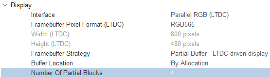
버퍼 위치 - 할당 방식 기준
권장되는 프레임 버퍼 할당 전략은 할당 방식 기준입니다. 이를 이용하면 TouchGFX Engine은 물리적 부분 프레임 버퍼 블록에 바로 그려지며 LTDC는 GFXMMU 주소 LUT를 읽습니다.
버퍼 위치 - 주소 기준
이 옵션은 렌더링을 가속화하기 위해 RGB888 프레임 버퍼 형식과 GPU2D(NeoChrome)를 사용하는 데 제한이 있는 일부 플랫폼에서만 권장됩니다.
일부 MCU는 렌더링 가속화를 위해 GPU2D(NeoChrome)를 사용하지만 24비트 RGB888 프레임 버퍼에 쓰는 것을 지원하지 않습니다. 이 경우 GFXMMU는 32비트 ARGB888 형식에서 물리적 프레임 버퍼 블록의 RGB888 형식으로 읽어오거나 쓰는 데이터를 패키징하는 데 사용됩니다.
Further reading
이를 활성화하기 위해서는 LTDC 픽셀 형식이 ARGB8888 프레임 버퍼 형식을 사용하고 GFXMMU의 가상 버퍼 중 하나인 GFXMMU_VIRTUAL_BUFFERX_BASE를 프레임 버퍼 주소로 사용하도록 설정되어야 합니다. GFXMMU에서 구성된 것과 동일한 GFXMMU 버퍼 주소를 사용하는 것이 중요합니다. 12 바이트의 블록 크기를 사용하도록 GFXMMU를 구성하고 아래에서 볼 수 있듯이 버퍼에 대한 패킹을 활성화합니다:
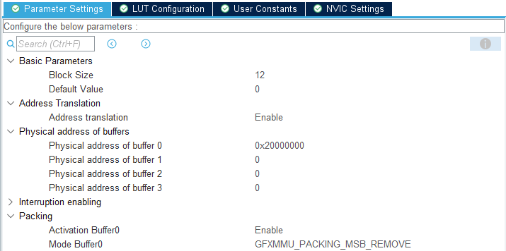
이러한 옵션은 TouchGFX Generator UI에 반영됩니다:
물리적 24비트 프레임 버퍼 메모리 영역은 링커 스크립트에서 올바른 크기(즉, 픽셀당 3바이트)로 정의해야 하며 이 영역의 시작 주소를 GFXMMU의 물리적 버퍼 주소를 구성하는 데 사용해야 합니다.
Note
지원되는 프레임 버퍼 전략
- 단일
- 이중
- 부분 - LTDC 기반 디스플레이
Further reading
단일
단일 프레임 버퍼 전략과 함께 LTDC 기반 디스플레이를 사용하면 HAL에 다음 코드가 생성되어 TouchGFX Engine이 디스플레이의 refresh 주기에 따라 렌더링 프로세스를 최적화할 수 있습니다.
TouchGFXGeneratedHAL.cpp
uint16_t TouchGFXGeneratedHAL::getTFTCurrentLine()
{
    // The CPSR register (bits 15:0) specify current line of TFT controller.
    uint16_t curr = (uint16_t)(LTDC->CPSR & LTDC_CPSR_CYPOS_Msk);
    uint16_t backPorchY = (uint16_t)(LTDC->BPCR & LTDC_BPCR_AVBP_Msk) + 1;

    // The semantics of the getTFTCurrentLine() function is to return a value
    // in the range of 0-totalheight. If we are still in back porch area, return 0.
    return (curr < backPorchY) ? 0 : (curr - backPorchY);
}
LTDC 인터럽트 핸들러에서 LTDC 프레임 버퍼 주소는 변경되지 않으며 디스플레이 refresh 주기가 활성 영역을 벗어날 때(디스플레이가 프레임 버퍼의 마지막 줄을 읽는 시점) TouchGFX Engine은 현재 프레임의 렌더링을 마칠 수 있습니다.
참조 구현
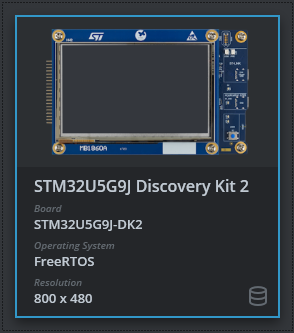
TouchGFX Board Setup STM32U5G9J 디스커버리 키트에는 이중 프레임 버퍼 전략의 참조 구현이 포함됩니다. TouchGFX Generator에서 프레임 버퍼 전략을 단일로 변경하고 코드를 생성하여 단일 프레임 버퍼 전략 사용 예제를 확인할 수 있습니다:
이중
이중 프레임버퍼 전략과 함께 LTDC 기반 디스플레이를 사용할 경우 LTDC 프레임버퍼 주소가 LTDC 인터럽트 핸들러의 다른 프레임버퍼로 변경됩니다. 이를 이용하면 TouchGFX Engine이 LTDC 프레임버퍼 주소가 변경된 직후에 다음 프레임을 렌더링할 수 있으며 그동안 LTDC는 다른 프레임버퍼에서 현재 프레임을 읽고 있습니다.
참조 구현
TouchGFX Board Setup STM32U5G9J 디스커버리 키트 2에는 참조 구현이 포함됩니다:
부분 - LTDC 기반 디스플레이
부분 프레임 버퍼 전략과 함께 LTDC 기반 디스플레이를 사용하는 것은 단일 프레임 버퍼 전략을 사용하는 것과 유사하나 TouchGFX Engine은 부분 프레임 버퍼 블록에만 렌더링됩니다. 동일한 프레임 버퍼 블록이 디스플레이의 모든 부분을 렌더링하는 데 다시 사용되므로 화면 끊김 및 깨짐 현상이 발생하는 것을 방지하기 위해서는 렌더링 프로세스를 효율적으로 관리하는 것이 중요합니다. 이를 달성할 수 있도록 TouchGFX Generator는 HAL에서 다음 코드를 생성해 TouchGFX Engine이 LTDC 라인 인터럽트를 구성하게 할 수 있게 합니다. 이 인터럽트는 디스플레이의 다음 부분이 렌더링될 때 TouchGFX Engine에 신호를 보냅니다:
TouchGFXGeneratedHAL.cpp
void TouchGFXGeneratedHAL::waitForLTDCLines(uint16_t numberOfLines)
{
    // The CPSR register (bits 15:0) specify current line of TFT controller.
    uint16_t curr = LTDC->CPSR & LTDC_CPSR_CYPOS_Msk;

    // The AWCR register (10:0) specify the accumulated active height.
    uint16_t max = (LTDC->AWCR & LTDC_AWCR_AAH_Msk) - 1;

    // Calculate the line at which to configure the interrupt.
    curr += numberOfLines;
    if (curr > max)
    {
        curr -= max;
    }

    // Configure line interrupt
    HAL_LTDC_ProgramLineEvent(&hltdc, curr);

    // Wait for VSync signal, which fires on the line interrupt that we just configured.
    OSWrappers::waitForVSync();
}
TouchGFXGeneratedHAL::waitForLTDCLines(uint16_t) 함수는 TouchGFX Engine 그리기 루프에서 호출됩니다. 요청되는 라인의 구체적인 개수는 일련의 매개변수에 달려 있습니다. TouchGFX Generator에서 구성된 부분 블록의 수에 따라 적절한 기본값이 이러한 매개변수에 할당됩니다.
디스플레이의 모든 부분을 렌더링하는 데 프레임버퍼 블록이 재사용되므로, TouchGFX Engine에 디스플레이의 다음 부분을 렌더링하기 시작하라는 신호를 보내기 위해 VSYNC 신호가 사용됩니다. 이 신호는 일반적으로 LTDC 주사선이 활성 영역을 벗어났음을 알리는 데 사용됩니다:
TouchGFXGeneratedHAL.cpp
extern "C"
{
    void HAL_LTDC_LineEventCallback(LTDC_HandleTypeDef* hltdc)
    {
        OSWrappers::signalVSync();
    }
}
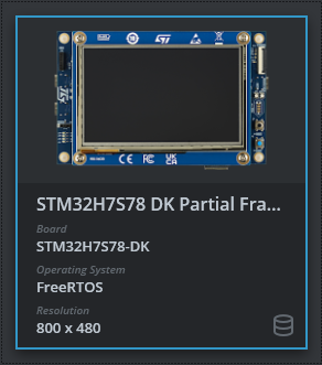
참조 구현
TouchGFX Board Setup STM32H7S78 DK 에뮬레이션된 프레임 버퍼에는 참조 구현이 포함됩니다.