MIPI-DSIコマンド・モード
このシナリオでは、ディスプレイ・シリアル・インタフェース(DSI)とGRAMを搭載したディスプレイを使用する場合に、コマンド・モードのMIPI DSIインタフェースとTouchGFX Generatorを設定する方法について説明します。 この記事で使用する例は、16ビットRGB565のフレームバッファ・フォーマットに対応するもので、STM32CubeMXの設定で実行されます。
Note
設定
LTDCの設定
- モード
Display TypeをRGB565(16 bits)- DSI Modeに設定
- レイヤの設定
Number of layersを1 layerに設定- スクリーン解像度を
Windows Position、Frame Buffer Line Length、およびFrame Buffer Number of Linesに設定 Layer 0 - Pixel FormatをRGB565に設定Layer 0 - Alpha constant for blendingを255に設定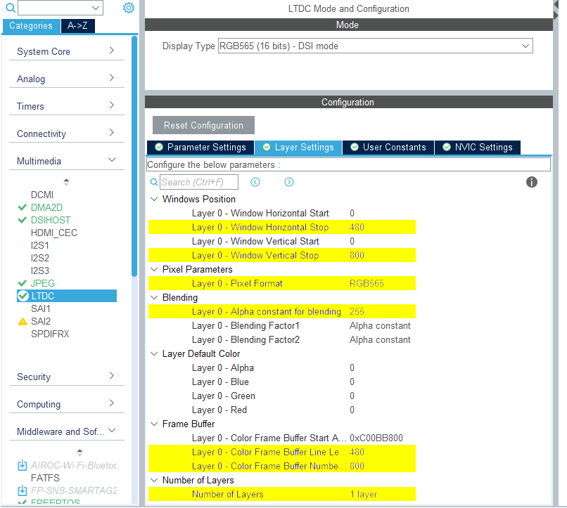
LTDCの設定
- NVICの設定
LTDC global interruptとLTDC global error interruptは両方とも不要なため、無効にする必要があります。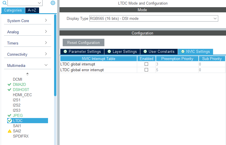
LTDC NVICの設定
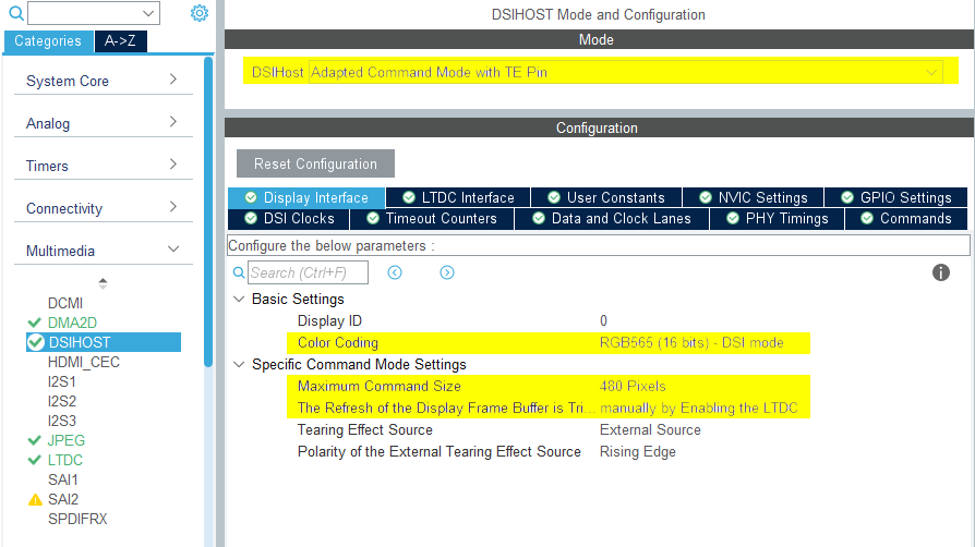
DSIHOSTの設定
- モード
DSIHostをAdapted Command Mode with TE Pinに設定
- ディスプレイ・インタフェース
Color CodingをRGB565(16 bits)- DSI modeに設定Maximum Command Sizeをディスプレイ幅相当の数値に設定The Refresh of the Display Frame Buffer is Triggeredをmanually by Enabling the LTDCに設定- 残りの設定は選択したLCD HWに応じて異なる
DSIHOSTの設定
- NVICの設定
DSI global interruptを有効にする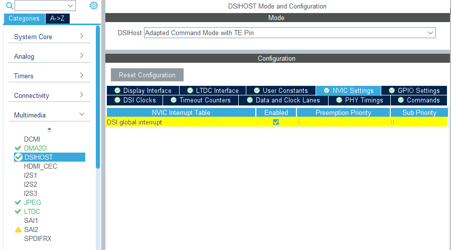
DSIHOST NVICの設定
TouchGFX Generator
- モード
- Graphics Applicationを有効にする
- TouchGFX Generator
Display / InterfaceをParallel RGB(LTDC)に設定(これはアプリケーションが通信する必要があるコントローラであるため)Application Tick SourceをCustomに設定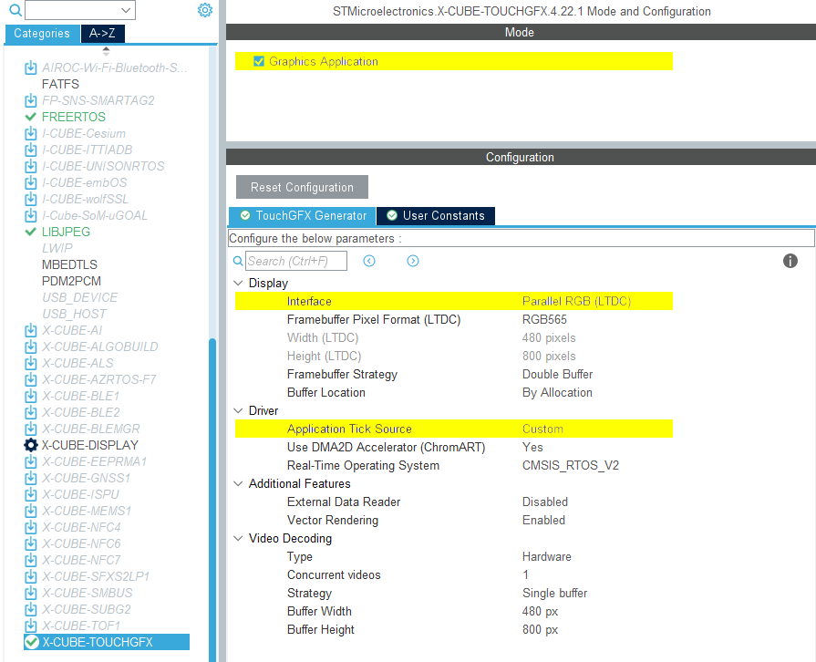
TouchGFX Generatorの設定
ユーザ・コード
TouchGFX Generatorでは部分的なTouchGFX ALしか生成できません。これは、 DSIホスト・コントローラを介してフレームバッファ・メモリからディスプレイにピクセルを転送し、ディスプレイがTouchGFX Engineと同期するようにLTDCを設定するものです。 ただし、これを実行するために必要なすべてのハンドルは、TouchGFX Generatorによって生成されます。
一般的に、GRAMを内蔵したディスプレイの場合、生成されたTouchGFX HALハンドルのTouchGFXHAL.cppにおける実装では、以下の手順を実行して、ピクセルをディスプレイに転送し、ディスプレイとTouchGFX Engineを同期する必要があります。
- 「VSYNC」(ティアリング効果(TE)信号と呼ばれることもあります)を待ち、TouchGFX Engineに信号を送ります。
- 再描画されるフレームバッファの領域に基づいて、この領域に対応するGRAM内の場所に、「ディスプレイ・カーソル」および「アクティブ・ウィンドウ」(更新されるディスプレイ領域)を移動します。
- 送られてくるピクセル・データをGRAMに書き込む準備を整えます。 フレームバッファ戦略と使用するディスプレイ・インタフェースに応じて、これはフレームバッファのポインタのスワッピング、TouchGFX Engineの信号伝達、または前の転送の完了を待つことであったりします。
- ピクセル・データを送信します。
使用するディスプレイとフレームバッファ戦略によって、上記の手順の実装方法は異なります。
DSIコマンド・モードのインタフェースで特に必要になると思われるいくつかの調整を以下に示します。
DSIHOST / LTDCの初期化シーケンス
MX_DSIHOST_DSI_Init()の呼出しは、MX_LTDC_Init()の前に行う必要があります。 これはSTM32CubeMXで処理します。 正しくない場合は、ユーザ・コード・セクションで必ず順序を修正してください。
HAL_DSI_Start()の呼び出し後、DSIHOSTクロックをDSIPHYソースに切り替えます。
static void MX_DSIHOST_DSI_Init(void)
{
  ...
  /* Switch to DSI PHY PLL clock */
  RCC_PeriphCLKInitTypeDef PeriphClkInit;
  PeriphClkInit.PeriphClockSelection = RCC_PERIPHCLK_DSI;
  PeriphClkInit.DsiClockSelection    = RCC_DSICLKSOURCE_DSIPHY;
  HAL_RCCEx_PeriphCLKConfig(&PeriphClkInit);
  /* USER CODE END DSIHOST_Init 2 */
  ...
}
ユーザは、MX_LTDC_Init()関数の末尾に、使用されたLCDコントローラに求められる固有の初期化コードを追加する必要があります。 そのコードは、DSI HAL APIのHAL_DSI_ShortWrite()とHAL_DSI_LongWrite()に基づくものになります。
  static void MX_LTDC_Init(void)
  {
    ...
    /* USER CODE BEGIN LTDC_Init 2 */
    // Specific LCD controller's initialization code
    ...

    // Exit Sleep Mode
    if (HAL_DSI_ShortWrite(&hdsi, 0, DSI_DCS_SHORT_PKT_WRITE_P0, DSI_EXIT_SLEEP_MODE, 0x00) != HAL_OK)
    {
      Error_Handler();
    }

    HAL_Delay(120);
    /* USER CODE END LTDC_Init 2 */
    ...
  }
DSIコマンド・モード用に更新されたTouchGFXHALクラス
アプリケーションで最初のフレームの描画を完了するまでMIPI DSIディスプレイがオンになるのを防ぐ1つの方法は、関数TouchGFXHAL::endFrameをガードして、TouchGFXが最初のフレームを描画するまでディスプレイをオフにしておくことです。 TouchGFXHAL::endFrame()を以下のように更新すると、PWM出力用に設定されたHWタイマを通して、LCDとそのバックライトを有効にできます。
void TouchGFXHAL::endFrame()
{
    if (!display_on)
    {
        display_on = true;
        /* Enable the LCD, Send Display on DCS command to display */
        HAL_DSI_ShortWrite(&hdsi, 0, DSI_DCS_SHORT_PKT_WRITE_P1, DSI_SET_DISPLAY_ON, 0x00);
        /* Start PWM Timer channel */
        (void)HAL_TIM_PWM_Start(&htim8, TIM_CHANNEL_2);
        /* Enable Backlight by setting Brightness to 100% */
        __HAL_TIM_SET_COMPARE(&htim8, TIM_CHANNEL_2, 2U * 100);
    }

    TouchGFXGeneratedHAL::endFrame();
}
サポートされるフレームバッファ戦略
- シングル
- ダブル
- パーシャル - GRAMディスプレイ
Further reading
通常、DSIコマンド・モードは、ディスプレイがピクセルをスキャンするよりも速くピクセルをGRAMに転送するように十分な広さの帯域幅を備えています。 これはFMCパラレル・ディスプレイ・インタフェースとよく似ています。 したがって、DSIコマンド・モードでTouchGFX ALを動作させるための実装手順は、FMCパラレル・ディスプレイ・インタフェースとよく似ています。
Further reading
シングル
現在のところ、TouchGFX Board Supportには、DSIコマンド・モードを使用したシングル・バッファに関するリファレンス実装が含まれていません。 セットアップは「FMCシングル・バッファ」のセットアップと似ていますが、FMCではなくDSIコマンド・モードのドライバ機能を使用します。
ダブル
現在のところ、TouchGFX Board Supportには、DSIコマンド・モードを使用したダブル・バッファに関するリファレンス実装が含まれていません。 セットアップは「FMCダブル・バッファ」のセットアップと似ていますが、FMCではなくDSIコマンド・モードのドライバ機能を使用します。
パーシャル - GRAMディスプレイ
現在のところ、TouchGFX Board Supportには、DSIコマンド・モードを使用したパーシャル - GRAMディスプレイに関するリファレンス実装が含まれていません。 セットアップは「FMCパーシャル - GRAMディスプレイ」のセットアップと似ていますが、FMCではなくDSIコマンド・モードのドライバ機能を使用します。