MIPI-DSI Command Mode
This scenario describes how to configure MIPI DSI interface in Command Mode and TouchGFX Generator when using a display with a Display Serial Interface (DSI) and GRAM. The example used in this article will be for 16-bit RGB565 frame buffer format and goes through configurations in STM32CubeMX.
Note
Configuration
LTDC Configuration
- Mode
- Set
Display Typeto RGB565 (16 bits) - DSI Mode
- Set
- Layer Settings
- Set
Number of layersto 1 layer - Set the screen resolution in
Windows PositionandFrame Buffer Line LengthandFrame Buffer Number of Lines - Set
Layer 0 - Pixel Formatto RGB565 - Set
Layer 0 - Alpha constant for blendingto 255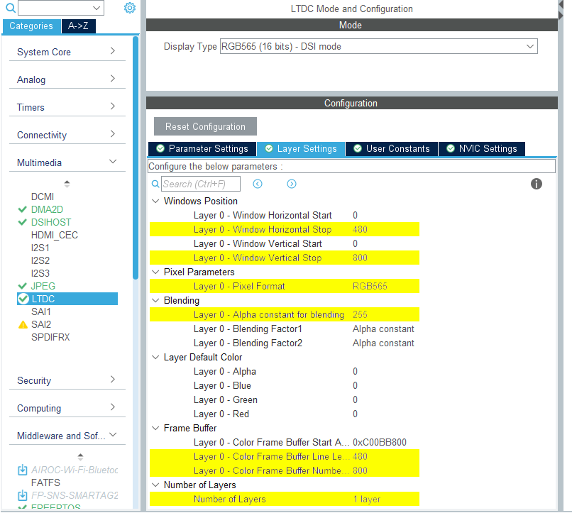
LTDC Configuration
- Set
- NVIC Settings
- Both
LTDC global interruptandLTDC global error interruptare not needed, and should be disabled.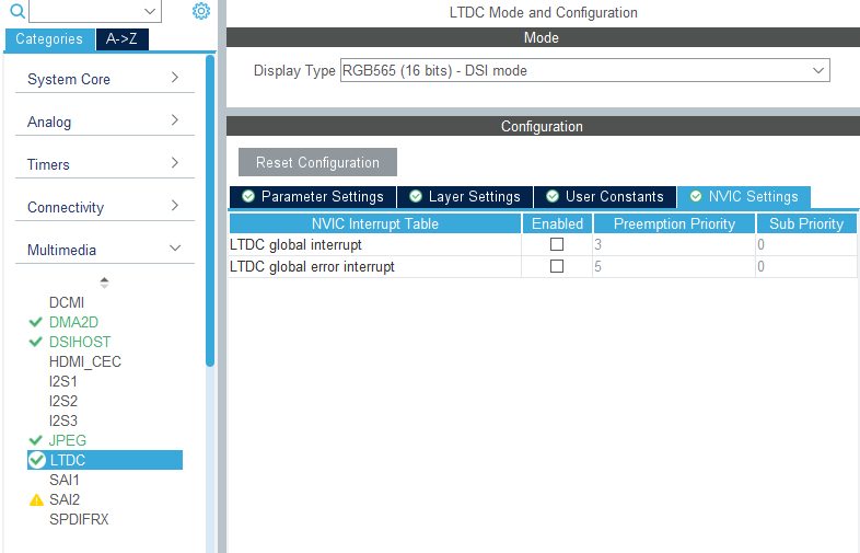
LTDC NVIC Settings
- Both
DSIHOST Configuration
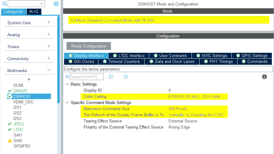
- Mode
- Set
DSIHostto Adapted Command Mode with TE Pin
- Set
- Display Interface
- Set
Color Codingto RGB565 (16 bits) - DSI mode - Set
Maximum Command Sizeto a number on the order of the width of the display - Set
The Refresh of the Display Frame Buffer is Triggeredto manually by Enabling the LTDC - Remaining configurations depends on the selected LCD HW
DSIHOST Configuration
- Set
- NVIC Settings
- Enable
DSI global interrupt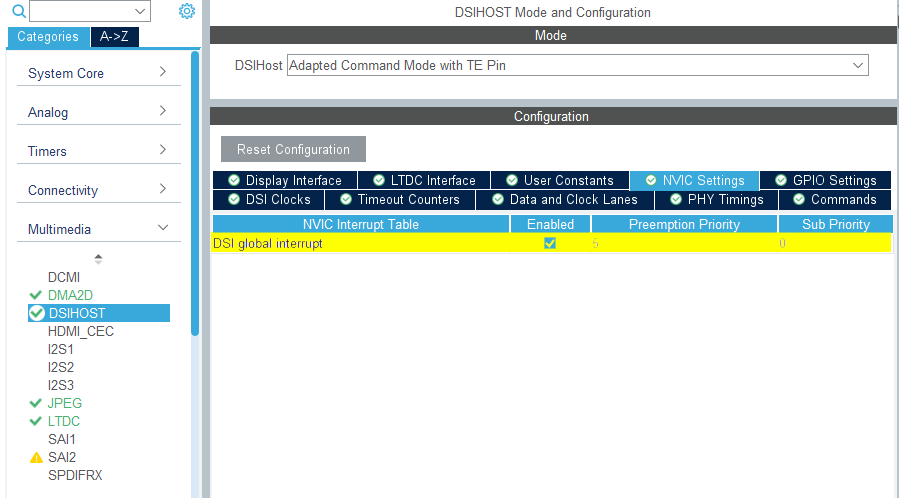
DSIHOST NVIC Settings
- Enable
TouchGFX Generator
- Mode
- Enable Graphics Application
- TouchGFX Generator
- Set
Display / Interfaceto Parallel RGB (LTDC) since this is still the controller the application needs to communicate with. - Set
Application Tick Sourceto Custom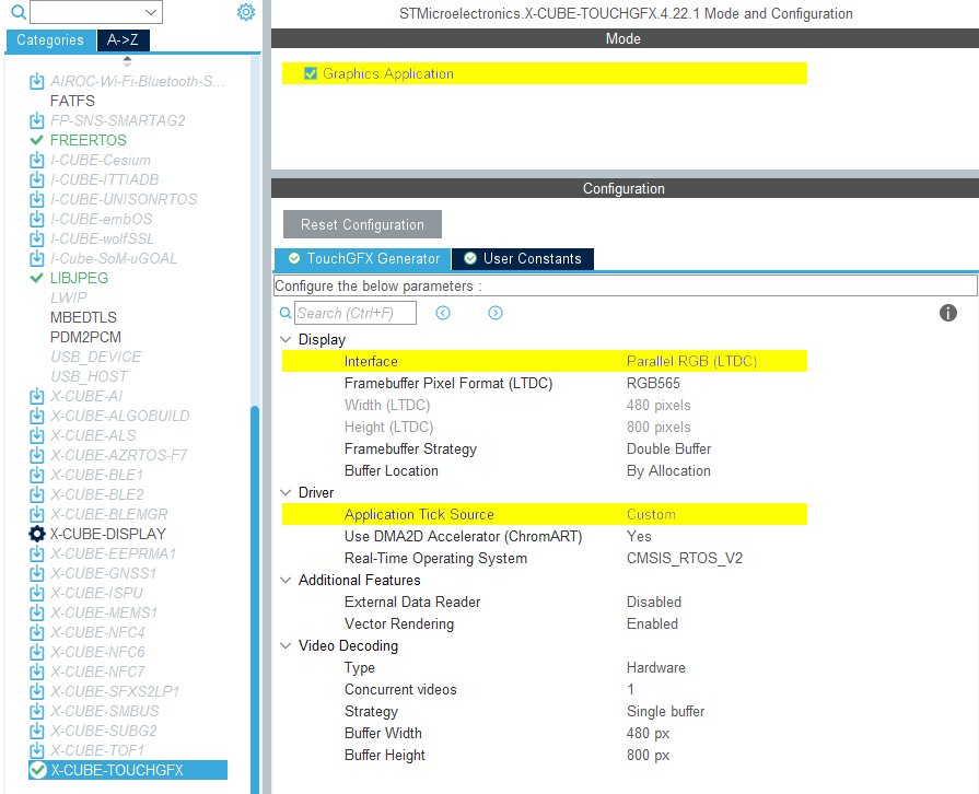
TouchGFX Generator Configuration
- Set
User Code
The TouchGFX Generator can only generate a partial TouchGFX AL that configures the LTDC to transfer pixels through the DSI Host controller from the framebuffer memory to the display and synchronize the display with the TouchGFX Engine. However, all necessary handles to accomplish this are generated by the TouchGFX Generator.
Generally, for displays with embedded GRAM, the implementation of the generated TouchGFX HAL handles in TouchGFXHAL.cpp should perform the following steps to transfer pixels to the display and synchronize the display with the TouchGFX Engine:
- Wait for "VSYNC" (sometimes called Tearing Effect (TE) signal) to signal the TouchGFX Engine.
- Based on the area of the framebuffer to be redrawn, move the "display cursor" and "active window" (the region of the display being updated) to a place in GRAM that matches this area.
- Prepare to write incoming pixel data to GRAM. Depending on the framebuffer strategy and display interface used, this could be swapping framebuffer pointers, signaling TouchGFX Engine, or waiting for previous transfers to complete.
- Send pixel data.
Depending on the display used and the framebuffer strategy, the implementation of the above steps will vary.
Some of the adjustments that may be needed specifcally for DSI Command Mode interfaces are described below.
DSIHOST / LTDC Initialization sequence
The call to MX_DSIHOST_DSI_Init() must be done before MX_LTDC_Init(). This should be handled by STM32CubeMX.
If this is not correct, take care to fix the order in a user code section.
After calling HAL_DSI_Start(), switch DSIHOST clock to the DSIPHY source:
static void MX_DSIHOST_DSI_Init(void)
{
  ...
  /* Switch to DSI PHY PLL clock */
  RCC_PeriphCLKInitTypeDef PeriphClkInit;
  PeriphClkInit.PeriphClockSelection = RCC_PERIPHCLK_DSI;
  PeriphClkInit.DsiClockSelection    = RCC_DSICLKSOURCE_DSIPHY;
  HAL_RCCEx_PeriphCLKConfig(&PeriphClkInit);
  /* USER CODE END DSIHOST_Init 2 */
  ...
}
User has to add the required initialization code specific to the used LCD controller at the end of the MX_LTDC_Init() function.
That code will be based on the DSI HAL APIs HAL_DSI_ShortWrite() and HAL_DSI_LongWrite():
  static void MX_LTDC_Init(void)
  {
    ...
    /* USER CODE BEGIN LTDC_Init 2 */
    // Specific LCD controller's initialization code
    ...

    // Exit Sleep Mode
    if (HAL_DSI_ShortWrite(&hdsi, 0, DSI_DCS_SHORT_PKT_WRITE_P0, DSI_EXIT_SLEEP_MODE, 0x00) != HAL_OK)
    {
      Error_Handler();
    }

    HAL_Delay(120);
    /* USER CODE END LTDC_Init 2 */
    ...
  }
Updated TouchGFXHAL class for DSI Command Mode
One way to prevent the MIPI DSI display from turning on until the first frame in the application has beem rendered is to guard the function TouchGFXHAL::endFrame to keep the display off until first frame is rendered by TouchGFX. The TouchGFXHAL::endFrame() could be updated as below, to enable the LCD and its Backlight through a HW Timer configured for PWM output.
void TouchGFXHAL::endFrame()
{
    if (!display_on)
    {
        display_on = true;
        /* Enable the LCD, Send Display on DCS command to display */
        HAL_DSI_ShortWrite(&hdsi, 0, DSI_DCS_SHORT_PKT_WRITE_P1, DSI_SET_DISPLAY_ON, 0x00);
        /* Start PWM Timer channel */
        (void)HAL_TIM_PWM_Start(&htim8, TIM_CHANNEL_2);
        /* Enable Backlight by setting Brightness to 100% */
        __HAL_TIM_SET_COMPARE(&htim8, TIM_CHANNEL_2, 2U * 100);
    }

    TouchGFXGeneratedHAL::endFrame();
}
Supported Framebuffer Strategies
- Single
- Double
- Partial - GRAM display
Further reading
DSI Command Mode usually has a high enough bandwidth to transfer pixels to GRAM fast than the display scans the pixels. This is very similar to to the FMC Parallel display interface. Therefore, the implementation steps for a working TouchGFX AL for DSI Command Mode is very similar to the FMC Parallel display interface.
Further reading
Single
Currently, no TouchGFX Board Support have a reference implementation for Single buffering with DSI Command Mode. The setup would be similar to FMC Single buffer setup, but using DSI Command Mode driver functions instead of FMC.
Double
Currently, no TouchGFX Board Support have a reference implementation for Double buffering with DSI Command Mode. The setup would be similar to FMC Double buffer setup, but using DSI Command Mode driver functions instead of FMC.
Partial - GRAM display
Currently, no TouchGFX Board Support have a reference implementation for Partial - GRAM display with DSI Command Mode. The setup would be similar to FMC Partial - GRAM display setup, but using DSI Command Mode driver functions instead of FMC.