MIPI-DSI Video Mode
이 시나리오는 Display Serial Interface(DSI)가 탑재된 디스플레이를 사용할 때 Video Mode 및 TouchGFX Generator에서 STM32 DSIHOST를 구성하는 방법을 설명합니다.
이 문서에서 사용되는 예제는 24비트/RGB888 프레임 버퍼 형식에 대한 것으로, STM32CubeMX의 구성을 살펴보고 생성된 코드를 예로 들어 설명합니다.
구성
LTDC 구성
- 모드
Display Type을 RGB888(24 bits) - DSI Mode로 설정
- Layer Settings
Number of layers를 1 layer로 설정Layer 0 - Pixel Format을 RGB888로 설정Layer 0 - Alpha constant for blending을 255로 설정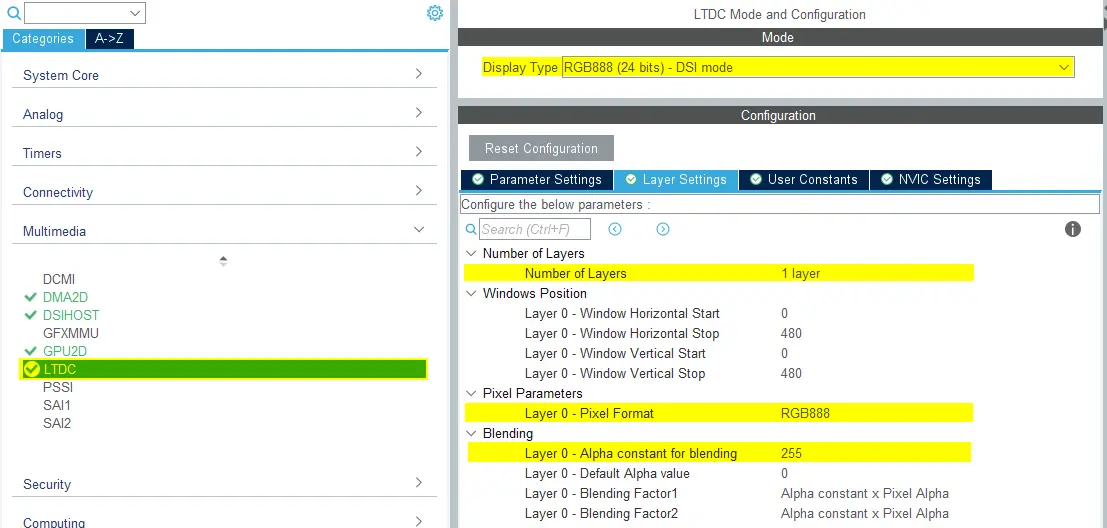
LTDC 구성
- NVIC 설정
- LCD-TFT 전역 인터럽트 활성화
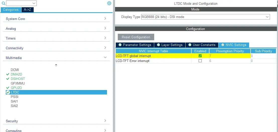
LTDC NVIC 설정
- LCD-TFT 전역 인터럽트 활성화
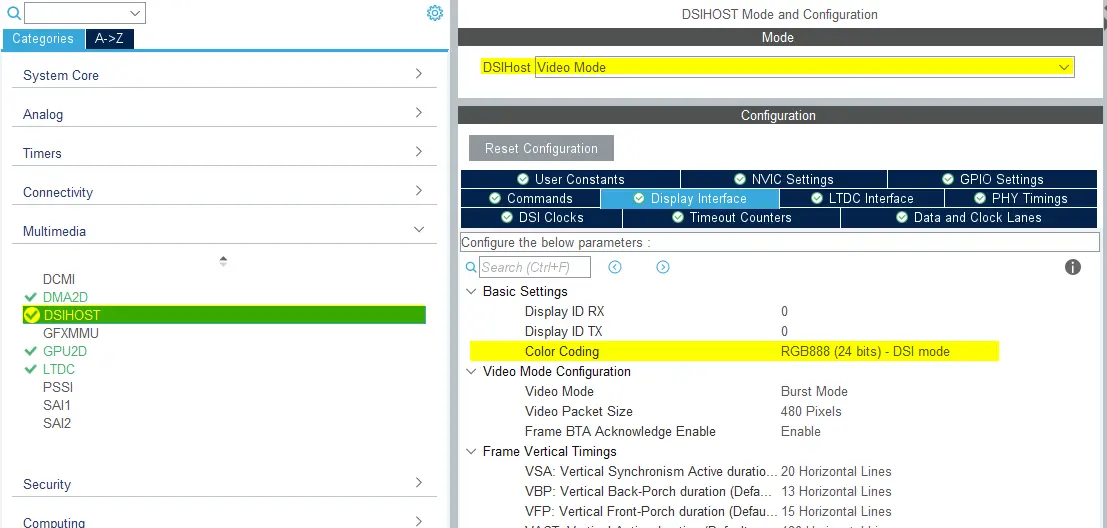
DSIHOST 구성
- 모드
DSIHost를 _*Video Mode**로 설정
- 디스플레이 인터페이스
Color Coding을 RGB888 (24 bits) - DSI mode로 설정- 나머지 구성은 선택한 LCD HW에 따라 다릅니다.
DSIHOST 구성
- NVIC 설정
- DSIHOST 전역 인터럽트는 필요하지 않기 때문에 비활성화되어야 합니다.
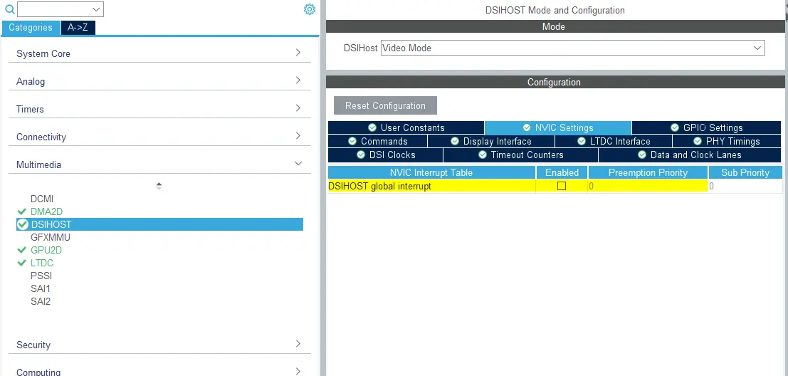
DSIHOST NVIC 설정
- DSIHOST 전역 인터럽트는 필요하지 않기 때문에 비활성화되어야 합니다.
TouchGFX Generator
- 모드
- Graphics Application 활성화
- TouchGFX Generator
Display / Interface를 Parallel RGB (LTDC)로 설정(여전히 애플리케이션이 통신해야 하는 컨트롤러이기 때문)Application Tick Source를 LTDC로 설정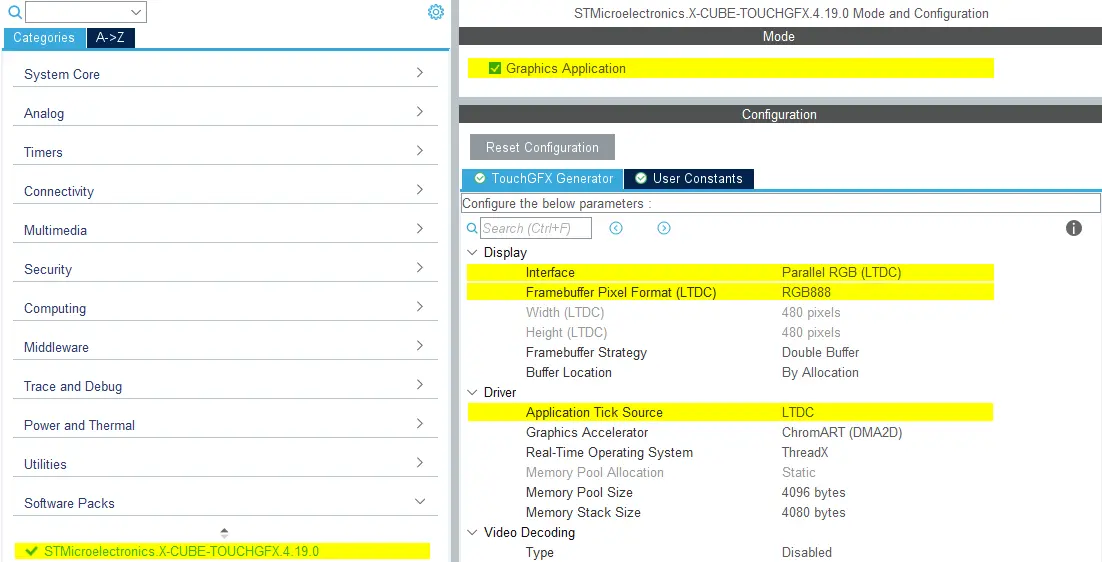
TouchGFX Generator 구성
사용자 코드
TouchGFX Generator는 DSI Host 컨트롤러를 통해 프레임 버퍼 메모리에서 디스플레이로 픽셀을 전송하고 디스플레이를 TouchGFX Engine과 동기화할 수 있도록 LTDC를 구성하는 전체 TouchGFX AL을 생성할 수 있습니다. 아래 설명된 바와 같이 소소한 조정만 필요할 수 있습니다.
DSIHOST / LTDC 초기화 시퀀스
MX_DSIHOST_DSI_Init()에 대한 호출은 MX_LTDC_Init()보다 먼저 이루어져야 합니다. 이 호출은 STM32CubeMX에서 처리해야 합니다. 이것이 올바르지 않다면 사용자 코드 섹션에서 순서를 수정하세요.
HAL_DSI_Start()를 호출한 후, DSIHOST 클록을 DSIPHY 소스로 전환합니다:
static void MX_DSIHOST_DSI_Init(void)
{
  ...
  /* Switch to DSI PHY PLL clock */
  RCC_PeriphCLKInitTypeDef PeriphClkInit;
  PeriphClkInit.PeriphClockSelection = RCC_PERIPHCLK_DSI;
  PeriphClkInit.DsiClockSelection    = RCC_DSICLKSOURCE_DSIPHY;
  HAL_RCCEx_PeriphCLKConfig(&PeriphClkInit);
  /* USER CODE END DSIHOST_Init 2 */
  ...
}
사용자는 MX_LTDC_Init() 함수의 끝에 사용된 LCD 컨트롤러에 필요한 초기화 코드를 추가해야 합니다. 해당 코드는 DSI HAL API HAL_DSI_ShortWrite() 및 HAL_DSI_LongWrite()를 기반으로 합니다.
  static void MX_LTDC_Init(void)
  {
    ...
    /* USER CODE BEGIN LTDC_Init 2 */
    // Specific LCD controller's initialization code
    ...

    // Exit Sleep Mode
    if (HAL_DSI_ShortWrite(&hdsi, 0, DSI_DCS_SHORT_PKT_WRITE_P0, DSI_EXIT_SLEEP_MODE, 0x00) != HAL_OK)
    {
      Error_Handler();
    }

    HAL_Delay(120);
    /* USER CODE END LTDC_Init 2 */
    ...
  }
DSI 비디오 모드에서 TouchGFXHAL 클래스 업데이트
LTDC 인터럽트를 위해 생성된 코드는 병렬 RGB 디스플레이 인터페이스를 사용할 때 생성되는 코드와 동일합니다.
이 애플리케이션의 첫 번째 프레임을 렌더링할 때까지 MIPI DSI 디스플레이가 켜지지 않게 할 수 있는 한 가지 방법은 TouchGFX에서 첫 번째 프레임을 렌더링할 때까지 디스플레이를 꺼진 상태로 유지하도록 TouchGFXHAL::endFrame 함수를 보호하는 것입니다. TouchGFXHAL::endFrame()을 아래와 같이 업데이트해서 PWM 출력용으로 구성된 HW 타이머를 통해 LCD와 그 백라이트를 활성화할 수 있습니다.
void TouchGFXHAL::endFrame()
{
    if (!display_on)
    {
        display_on = true;
        /* Enable the LCD, Send Display on DCS command to display */
        HAL_DSI_ShortWrite(&hdsi, 0, DSI_DCS_SHORT_PKT_WRITE_P1, DSI_SET_DISPLAY_ON, 0x00);
        /* Start PWM Timer channel */
        (void)HAL_TIM_PWM_Start(&htim8, TIM_CHANNEL_2);
        /* Enable Backlight by setting Brightness to 100% */
        __HAL_TIM_SET_COMPARE(&htim8, TIM_CHANNEL_2, 2U * 100);
    }

    TouchGFXGeneratedHAL::endFrame();
}
지원되는 프레임 버퍼 전략
- 단일
- 이중
- 부분 - LTDC 기반 디스플레이
Further reading
참조 구현
TouchGFX Board Setup STM32U5G9J DK1에는 RGB888 24비트 프레임 버퍼 형식으로 DSI 비디오 모드를 실행하는 참조 구현이 포함됩니다.