Display
The Display group contains configurations related to display, such as interface, dimensions and buffering strategies.
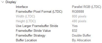
TouchGFX Generator Display settings
Interface and dimensions
Multiple display interfaces are usable today with STM32 microcontrollers, e.g.:
- Parallel RGB (LTDC)
- MIPI DSI
- FMC
- SPI
In the case of MCUs with a display connected to an LTDC or FMC TouchGFX Generator can generate code to transfer the framebuffer to the connected display. For DSI and SPI interfaces drivers must be implemented by developers themselves.
Further reading
Framebuffer Pixel Format
The following framebuffer pixel formats are currently supported by TouchGFX Generator. All options are available when using "Custom" display interface, otherwise options are restricted to display controller settings (e.g. configuring the LTDC Framebuffer format to "RGB565" will limit the options to "RGB565" in TouchGFX Generator).
- BW (1bpp)
- Grey2 (2bpp)
- Grey4 (4bpp)
- ABRG2222 (8bpp)
- ARGB2222 (8bpp)
- BGRA2222 (8bpp)
- RGBA2222 (8bpp)
- RGB565 (16bpp)
- RGB888 (24bpp)
- ARGB8888 (32bpp)
- XRGB8888 (32bpp)
Note
Framebuffer Stride
For some display interfaces (e.g. MIPI-DSI) having a larger framebuffer stride than the actual width of the display can increase the data transfer rate to the display if the larger stride is better aligned with the data packet size. Use of a larger framebuffer stride can be configured as:
- No - The framebuffer stride and display width are equal in size.
- Yes - Allows the user to specify a framebuffer stride length.
Buffering Strategies & Location
The following frame buffer strategies can be configured through TouchGFX generator:
- Single Buffer - Use only one application frame buffer. Possibly limits performance but uses less memory. Can be used with the "Buffer Location" configuration to place it in internal RAM. For further optimization the user can define a function that returns the current line being processed by the display controller. This method is used by the framework to allow updates to memory that has already been transferred to the display during this frame.
- Double Buffer - Use two frame buffers. Usually allows for better performance at the cost of memory.
- Partial Buffer - GRAM display - Use one or more user defined chunks of memory as the frame buffer, which are transferred to the GRAM on the display. This strategy is targeted at low cost solutions that do not rely on external RAM, but have displays for which a full frame buffer would exceed available memory.
- Partial Buffer - LTDC driven display - Use a single block of memory that a power-of-2 fraction of the display size, e.g., 1/2, 1/4 or 1/8. This strategy is targeted platforms that do not have external RAM and/or large display resolutions. A LTDC driven display and GFXMMU is required for this strategy.
In the case of Single Buffer, Double Buffer, and Partial Buffer - LTDC driven display users are allowed to configure their location through the "Buffer Location" configuration which offers the following options:
- By Allocation - Lets the linker place frame buffer memory according to linker script. Default is in internal RAM.
- By Address - Allows the user to define one (Single) or two (Double) frame buffer addresses.
The Partial Buffer - GRAM display strategy allows the user to define the following parameters:
- Number of blocks (always placed in internal RAM)
- Block size (bytes)
The Partial Buffer - LTDC driven display strategy allows the user to define the following parameter:
- Number of Partial Blocks (default is 4, meaning a framebuffer block 1/4 the size of the display)
To understand some core concepts regarding framebuffer strategies, refer to the Framebuffer Strategies article.
Several scenarios describe how to get started with different display interfaces and framebuffer strategies with concrete examples: