FMC Display Interface
This scenario describes how to configure the STM32 FMC (Flexible Memory Controller) and TouchGFX Generator when using a display with a FMC parallel interface and GRAM.
Note
Configuration
FMC configuration
Enable the FMC from the Connectivity group in the STM32CubeMX category list. From here, one of the available FMC Banks must be configured to LCD Interface. This is done by setting the Memory type to LCD Interface in STM32CubeMX. The number of parallel data lines used to transfer pixels to the display is also selected here, i.e., 16-bit or 8-bit parallel interface.
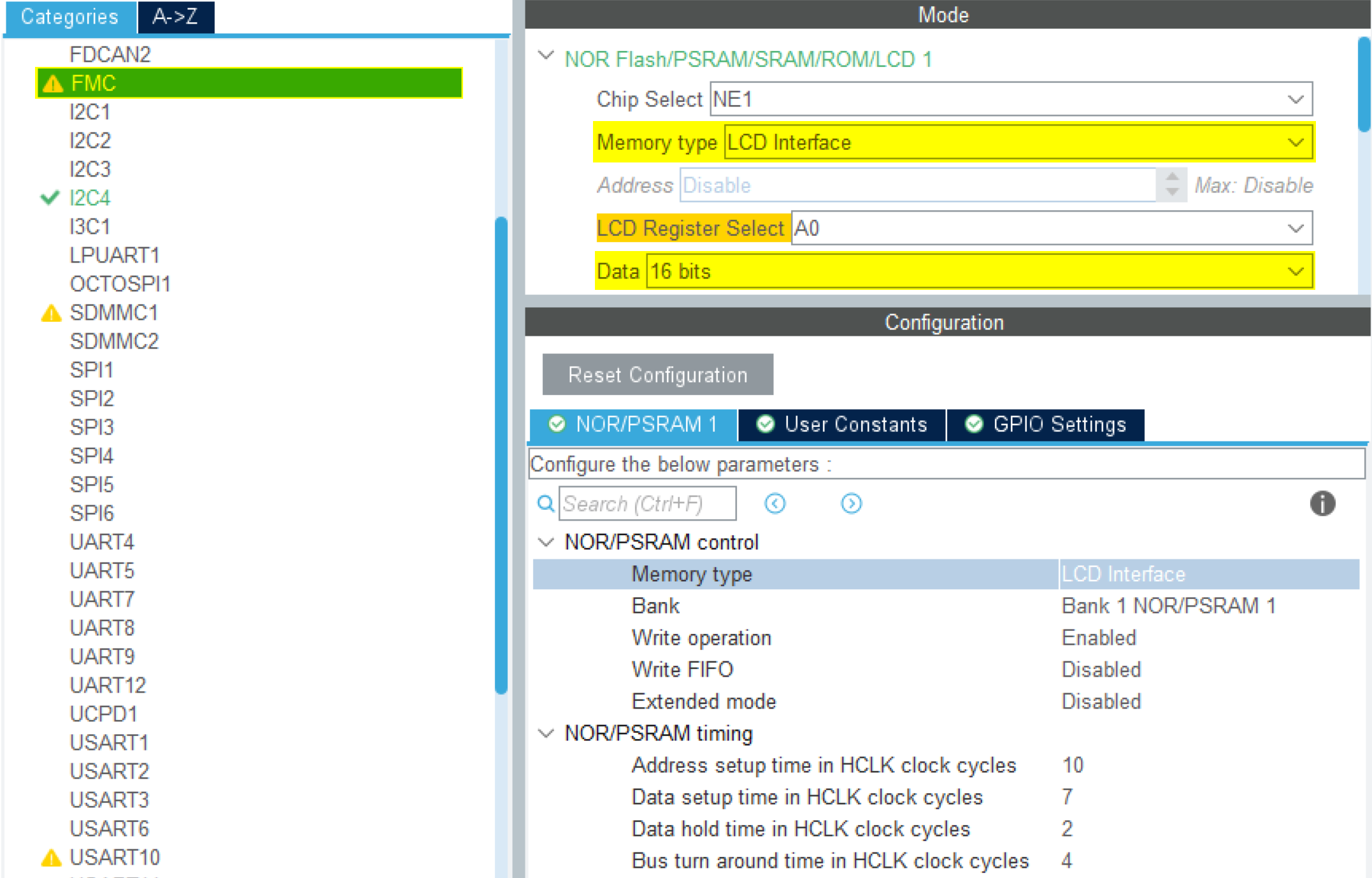
FMC Bank Configuration
Be sure to configure the timings correctly for the display used. Verify the base address of the FMC for your MCU and the bank used to interface with the display.
TouchGFX Generator
Display Interface: Parallel RGB (FMC)
If using a 16-bit parallel interface, the TouchGFX Generator can generate a HAL which provide a simple API with default implementations to Read/Write data and registers to the LCD:
TouchGFXGeneratedHAL.cpp
...
    /**
     * @brief  Initialize the LCD IO.
     * @param  None
     * @retval None
     */
    __weak void LCD_IO_Init(void)
    {
        // Already Done by MX_FMC_Init()
    }

    /**
     * @brief  Writes data on LCD data register.
     * @param  Data: Data to be written
     * @retval None
     */
    __weak void LCD_IO_WriteData(uint16_t RegValue)
    {
        /* Write 16-bits Reg */
        FMC_BANK1_WriteData(RegValue);
    }
...
See file TouchGFXGeneratedHAL.cpp for the full generated code. These functions are defined as __weak so that developers can override them in their own HAL implementation if needed.
If a FMC bank is correctly configured, it can be selected in the TouchGFX Generator:
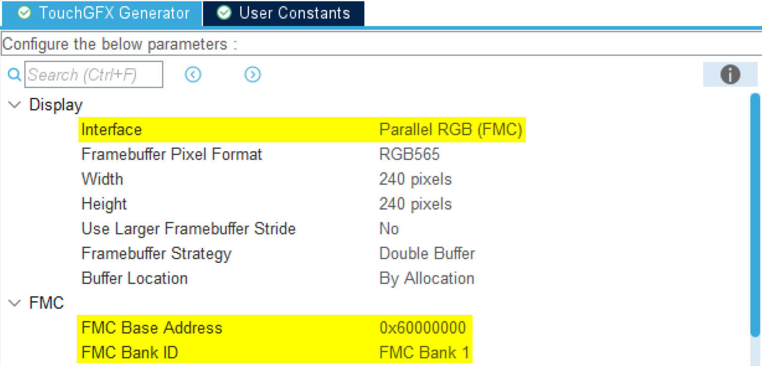
Display Interface - Parallel RGB (FMC)
Display Interface: Custom
If using a 8-bit FMC interface (or another serial interface such as SPI or DSI Command mode), the Custom Display Interface must be selected in the TouchGFX Generator. This means a full HAL cannot be automatically generated, so the developer must implement functionality to configure and transfer pixels from the framebuffer memory to the display manually. All necessary handles to accomplish this are generated by the TouchGFX Generator. Below shows how to select Custom.

Display Interface - Custom
Tip
DMA configuration
To minimize CPU load, a DMA channel can be configured to transfer pixel data from the framebuffer to the FMC. If using a 16-bit parallel interface, the generated LCD API can be overridden to do DMA transfers instead.
Alternatively, the API can be extended in TouchGFXHAL.cpp to include a DMA transfer functions. Below is an example of a GPDMA channel configuration for the FMC:
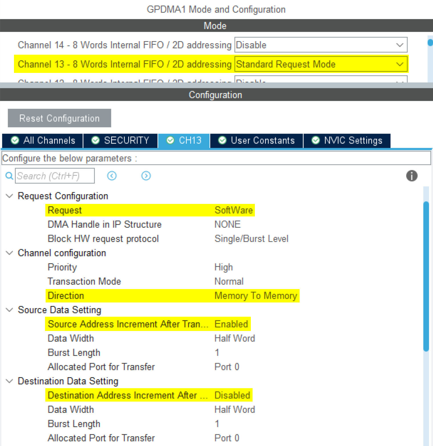
DMA configuration
The Request is set to Software since we need to program the requests in the HAL layer to transfer the framebuffer to the display. We enable Source Address Increment to move the framebuffer pointer and disable Destination Address Increment to always write to the FMC Bank memory address.
User Code
Generally, for displays with embedded GRAM, the implementation of the generated TouchGFX HAL handles in TouchGFXHAL.cpp should perform the following steps to transfer pixels to the display and synchronize the display with the TouchGFX Engine:
- Wait for "VSYNC" (sometimes called Tearing Effect (TE) signal) to signal the TouchGFX Engine.
- Based on the area of the framebuffer to be redrawn, move the "display cursor" and "active window" (the region of the display being updated) to a place in GRAM that matches this area.
- Prepare to write incoming pixel data to GRAM. Depending on the framebuffer strategy and display interface used, this could be swapping framebuffer pointers, signaling TouchGFX Engine, or waiting for previous transfers to complete.
- Send pixel data.
Depending on the display used and the framebuffer strategy, the implementation of the above steps will vary. The following sections describe how to implement these steps when using a GRAM display with FMC parallel interface.
Supported Framebuffer Strategies
- Single
- Double
- Partial - GRAM display
Further reading
Single
Transferring pixel data to the display using FMC parallel interface often provides a very high bandwidth. Because of this, many applications may update the framebuffer in a naive fashion, meaning that rendering of the next frame starts after the previous frame has been transferred to the display. A more optimal approach is to transfer the previous frame in smaller chunks, and signaling to the TouchGFX Engine to start rendering of the next frame in the framebuffer area that has been transferred so far. This emulates the concept of following the scanline from LTDC driven displays, only here we follow the transferline.
To enable optimal display transfer and rendering, the TouchGFX Engine must be set to use the correct framebuffer strategy and a delay function must be provided:
TouchGFXHAL.cpp
void TouchGFXHAL::initialize()
{
    // Other initialization code

    registerTaskDelayFunction(&OSWrappers::taskDelay);
    setFrameRefreshStrategy(REFRESH_STRATEGY_OPTIM_SINGLE_BUFFER_TFT_CTRL);

    TouchGFXGeneratedHAL::initialize();
}
To initiate a display transfer, an external interrupt generated by the displays TE signal is used to signal the TouchGFX Engine to start rendering the next frame and start transferring the previously rendered frame to the display. Typically, the TE signal is a pulse that signals the display scanline has left the active area on the Rising edge and enters again on the Falling edge. If the display transfer bandwidth is larger than the bandwidth the display scans pixels (which is often for case for FMC), we can safely start a transfer on the Rising edge of the TE signal without risking tearing. This is the case in the code below:
TouchGFXHAL.cpp
void HAL_GPIO_EXTI_Rising_Callback(uint16_t GPIO_Pin)
{
    if (GPIO_Pin == LCD_TE_Pin)
    {
        // VSync has occurred, increment TouchGFX engine vsync counter
        HAL::getInstance()->vSync();
        // VSync has occurred, signal TouchGFX engine
        OSWrappers::signalVSync();
        GPIO::set(GPIO::VSYNC_FREQ);

        if (refreshRequested)
        {
            refreshRequested = false;
            nextSendToDisplayLine = refreshMinLine;
            maxSendToDisplayLine = refreshMaxLine;
            sendNextFrameBufferBlockToDisplay();
        }
    }
}
Note
In the code above, the helper variables nextSendToDisplayLine and maxSendToDisplayLine are defining the region of the previous frame to be transferred to the display.
The values of these variables are updated by the TouchGFX Engine in TouchGFXHAL::flushFrameBuffer, which is called whenever a part of the framebuffer has been updated.
The framebuffer is also marked dirty, to signal that we need to transfer data on the next TE signal.
TouchGFXHAL.cpp
void TouchGFXHAL::flushFrameBuffer(const touchgfx::Rect& rect)
{
    // Calling parent implementation of flushFrameBuffer(const touchgfx::Rect& rect).
    TouchGFXGeneratedHAL::flushFrameBuffer(rect);

    // In the below code, the refreshMinLine and refreshMaxLine variables are updated to span the
    // smallest possible range, which covers all changes to the framebuffer.
    int rectMin = rect.y;
    int rectMax = rect.bottom();
    refreshMinLine = MIN(rectMin, refreshMinLine);
    refreshMaxLine = MAX(rectMax, refreshMaxLine);

    refreshRequested = true; // Signal that the framebuffer has been updated this tick
}
A helper function to send chunks of framebuffer pixels to the display must be implemented using FMC functions:
TouchGFXHAL.cpp
void sendNextFrameBufferBlockToDisplay()
{
    maxDrawLine = nextSendToDisplayLine; // Update the area that TouchGFX framework is allow to draw to based on the progress of the transfer

    const int32_t remainingLines = maxSendToDisplayLine - nextSendToDisplayLine;
    if (remainingLines > 0)
    {
        // The display transfer is not done. Start transfer of the next block
        const uint32_t sendBlockHeight = MIN(MAX_BLOCK_HEIGHT, remainingLines);
        setDisplayWindow(0, nextSendToDisplayLine, DISPLAY_WIDTH, sendBlockHeight);
        uint16_t* dataPtr = framebuffer + nextSendToDisplayLine * DISPLAY_WIDTH;
        uint32_t dataSize = DISPLAY_WIDTH * sendBlockHeight * 2;
        nextSendToDisplayLine += sendBlockHeight;
        LCD_IO_SendDataDMA((uint8_t*)dataPtr, dataSize);
    }
    else
    {
        // The display transfer is done. Allow drawing to the entire framebuffer
        maxDrawLine = DISPLAY_HEIGHT;
    }
}
In the code above, remainingLines is the number of lines left to transfer to the display. If there are lines left, we define sendBlockHeight to be the number of lines being transferred.
The constant MAX_BLOCK_HEIGHT limits the size of transfers. The variable maxDrawLine is the high watermark for the area that has been transferred, which determines the current line the TouchGFX Engine is allowed to draw to in the next frame.
This value is incremented as the transfers progresses, and is set to DISPLAY_HEIGHT when the transfer of the dirty region is complete to allow the TouchGFX Engine to complete the next frame. The TouchGFX Engine will query maxDrawLine to know how much of the framebuffer
it is allowed to update:
TouchGFXHAL.cpp
uint16_t TouchGFXHAL::getTFTCurrentLine()
{
    return maxDrawLine;
}
Once a block has been transferred, the transfer complete callback is used to initiate the next transfer:
TouchGFXHAL.cpp
static void DMA_TxCpltCallback(DMA_HandleTypeDef* hdma)
{
    if (hdma == DISPLAY_DMA)
    {
        sendNextFrameBufferBlockToDisplay();
    }
}
This is repeated until all of the dirty area of the framebuffer has been transferred to the display.
The above described cycles repeats when the next TE signal is received.
Reference implementation
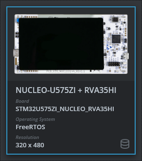
The TouchGFX Board Setup NUCLEO-U575ZI + RVA35HI includes a reference implementation of single framebuffer strategy with optimized rendering/transferring using FMC:
Double
Compared to single framebuffer, double buffering allows the TouchGFX Engine to freely write next frame into one framebuffer, while transferring the previous frame from the other framebuffer. This gives the most optimal render time, as it does not need to wait for the display transfers.
To initiate a display transfer, an external interrupt generated by the displays TE signal is used to signal the TouchGFX Engine to swap framebuffers and start rendering the next frame. The display is set to transfer the previously rendered frame to the display:
TouchGFXHAL.cpp
void LCD_SignalTearingEffectEvent(void)
{
    // VSync has occurred, increment TouchGFX engine vsync counter
    HAL::getInstance()->vSync();
    // VSync has occurred, signal TouchGFX engine
    OSWrappers::signalVSync();

    if (refreshRequested)
    {
        // Swap frame buffers immediately instead of waiting for the task to be scheduled in.
        // Note: task will also swap when it wakes up, but that operation is guarded and will not have
        // any effect if already swapped.

        touchgfx::HAL::getInstance()->swapFrameBuffers();

        // Set window, enable display reading to GRAM, transmit buffer using DMA
        setWindow(0, 0, 240, 240);
        LCD_IO_WriteReg(ST7789H2_WRITE_RAM);
        dmaCompleted = false;
        LCD_IO_SendDataDMA((uint8_t*)TFTframebuffer, (240 * 240 * 2));
    }
}
In the above code, the resolution of the display is 240x240 pixels (16-bit RGB565 framebuffer), so the window is set to the entire display area.
If bandwidth is limited, the windows can be made smaller to only encompass dirty regions. The TouchGFX HAL function TouchGFXHAL::flushFrameBuffer may be used for this purpose.
TouchGFX HAL functions TouchGFXHAL::beginFrame() and TouchGFXHAL::endFrame() are to request that a transfer must be done, i.e., the framebuffer is marked dirty.
TouchGFXHAL.cpp
bool TouchGFXHAL::beginFrame()
{
    refreshRequested = false;

    return TouchGFXGeneratedHAL::beginFrame();
}

void TouchGFXHAL::endFrame()
{
    TouchGFXGeneratedHAL::endFrame();

    if (frameBufferUpdatedThisFrame)
    {
        refreshRequested = true;
    }
}
The address of the framebuffer that is transferred to the display is maintained be the methods TouchGFXHAL::setTFTFrameBuffer() and TouchGFXHAL::getTFTFrameBuffer():
TouchGFXHAL.cpp
uint16_t* TouchGFXHAL::getTFTFrameBuffer() const
{
    return TFTframebuffer;
}

void TouchGFXHAL::setTFTFrameBuffer(uint16_t* address)
{
    TFTframebuffer = address;

    TouchGFXGeneratedHAL::setTFTFrameBuffer(address);
}
The pointer TFTframebuffer is used in the TE interrupt handler to set the source address of the windows being transferred to the display.
Reference implementation
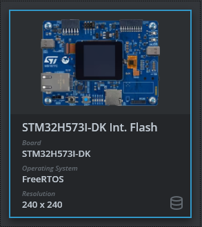
The TouchGFX Board Setup STM32H573-DK Int. Flash includes a reference implementation of double framebuffer strategy using FMC:
Partial - GRAM display
When choosing Partial - GRAM display framebuffer strategy in the TocuhGFX Generator, user must configure the number of partial framebuffer blocks and their sizes.
Code generated by the TouchGFX Generator will instantiate a FrameBufferAllocator to track the states of the partial framebuffer blocks and configure the framebuffer strategy:
TouchGFXGeneratedHAL.cpp
// Block Allocator for Partial Framebuffer strategy
static ManyBlockAllocator<2048, /* block size */
       3, /* number of blocks */
       2 /* bytes per pixel */
       > blockAllocator;

void TouchGFXGeneratedHAL::initialize()
{
    HAL::initialize();
    registerEventListener(*(Application::getInstance()));
    // Partial framebuffer strategy
    setFrameBufferAllocator(&blockAllocator);
    setFrameRefreshStrategy(HAL::REFRESH_STRATEGY_PARTIAL_FRAMEBUFFER);
}
Another class PartialFrameBufferManager handles the synchronization between the partial framebuffer blocks, the transferring of blocks, and the timing of the displays refresh rate.
The generated code makes use of the API exposed by the PartialFrameBufferManager to transfer the framebuffer blocks in the TouchGFXGeneratedHAL::flushFrameBuffer:
TouchGFXGeneratedHAL.cpp
void TouchGFXGeneratedHAL::flushFrameBuffer(const touchgfx::Rect& rect)
{
    HAL::flushFrameBuffer(rect);
    // Try transmitting a block
    PartialFrameBufferManager::tryTransmitBlock();
}
The PartialFrameBufferManager uses three functions to interact with
the display driver code. These must be implemented in the TouchGFX board setup:
TouchGFXGeneratedHAL.cpp
/**
 * Check if a Frame Buffer Block is beeing transmitted.
 */
int transmitActive()
{
    return touchgfxDisplayDriverTransmitActive();
}

/**
 * Check if a Frame Buffer Block ending at bottom may be sent.
 */
int shouldTransferBlock(uint16_t bottom)
{
    return touchgfxDisplayDriverShouldTransferBlock(bottom);
}

/**
 * Transmit a Frame Buffer Block.
 */
void transmitBlock(const uint8_t* pixels, uint16_t x, uint16_t y, uint16_t w, uint16_t h)
{
    touchgfxDisplayDriverTransmitBlock(pixels, x, y, w, h);
}
The code above forwards the calls to C functions that can be implemented in a display driver in TouchGFXHAL.cpp.
In the example below, the implementations call the FMC API functions with the parameters from the PartialFrameBufferManager:
TouchGFXHAL.cpp
extern "C" void touchgfxDisplayDriverTransmitBlock(const uint8_t* pixels, uint16_t x, uint16_t y, uint16_t w, uint16_t h)
{
    isTransmittingBlock = true;

    setDisplayWindow(x, y, w, h);

    LCD_IO_SendDataDMA((uint8_t*)pixels, w * h * 2);
}
The function touchgfxDisplayDriverTransmitActive simply returns the value of the global variable isTransmittingBlock:
TouchGFXHAL.cpp
extern "C" int touchgfxDisplayDriverTransmitActive()
{
    return isTransmittingBlock ? 1 : 0;
}
This value is reset in the Transfer Complete callback.
The function touchgfxDisplayDriverShouldTransferBlock checks if the display is ready to receive a new block. Partial framebuffer blocks are transmitted behind the display scanline.
For example if the displays scanline has scanned down to line 50, and the bottom of the block to be transferred is at line 70, then the TouchGFX Engine must wait until the display has progressed below
line 70 to start transferring the block. This is to avoid tearing on the display.
Many displays do not support this feature, so a hardware Timer can be used to estimate the line by incrementing a counter at every line. The rate at which the counter should be incremented should ideally be
every Frame Duration (ms) / Display Height (pixels), for example 16.67 ms / 320 pixels = 52.1 us per line. An example implementation of touchgfxDisplayDriverShouldTransferBlock using a Line Timer is shown below:
TouchGFXHAL.cpp
extern "C" int touchgfxDisplayDriverShouldTransferBlock(uint16_t bottom)
{
    // Only allow block transfer if the display has drawn past the bottom of the requested block (plus a margin of two lines)
    // A timer is used to estimate how many lines have been drawn by setting the prescaler so the tick rate matches the line draw rate
    uint16_t lastLineDrawn = LL_TIM_GetCounter(LINE_TIMER);
    return bottom + 2 < lastLineDrawn || tearingEffectCount > 0;
}
In the above code, the function returns true if the bottom (plus some margin) is smaller than the display line counter or if the tearingEffectCount is greater than 0.
If tearingEffectCount is greater than 0, this means that the display has emitted a TE signal, and is now at the same frame as the block to transfer (but behind in the display Y axis),
which means the block must be transferred.
Tip
The tearingEffectCount is incremented in the TE interrupt handler and the TouchGFX Engine is signaled to start rendering the next frame:
TouchGFXHAL.cpp
void HAL_GPIO_EXTI_Rising_Callback(uint16_t GPIO_Pin)
{
    if (GPIO_Pin == LCD_TE_Pin)
    {
        // Code to handle TE signal. Could be fine-tuning the display line timer frequency

        tearingEffectCount++;

        // VSync has occurred, increment TouchGFX engine vsync counter
        HAL::getInstance()->vSync();
        // VSync has occurred, signal TouchGFX engine
        OSWrappers::signalVSync();

        GPIO::set(GPIO::VSYNC_FREQ);
        startRenderingImmediately = true;
    }
}
We reset the tearingEffectCount when we start the next frame:
TouchGFXHAL.cpp
bool TouchGFXHAL::beginFrame()
{
    tearingEffectCount = 0;
    return TouchGFXGeneratedHAL::beginFrame();
}
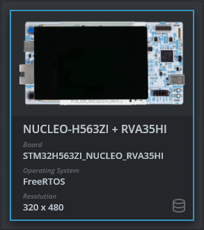
Reference implementation
The TouchGFX Board Setup NUCLEO-H563ZI + RVA35HI includes a reference implementation of partial framebuffer strategy using FMC and adaptive display line timer configuration: