MIPI-DSI Video Mode
This scenario describes how to configure a STM32 DSIHOST in Video Mode and TouchGFX Generator when using a display with Display Serial Interface (DSI).
The example used in this article will be for 24-bit RGB888 framebuffer format and goes through configurations in STM32CubeMX and exemplifies with generated code.
Configuration
LTDC Configuration
- Mode
- Set
Display Typeto RGB888 (24 bits) - DSI Mode
- Set
- Layer Settings
- Set
Number of layersto 1 layer - Set
Layer 0 - Pixel Formatto RGB888 - Set
Layer 0 - Alpha constant for blendingto 255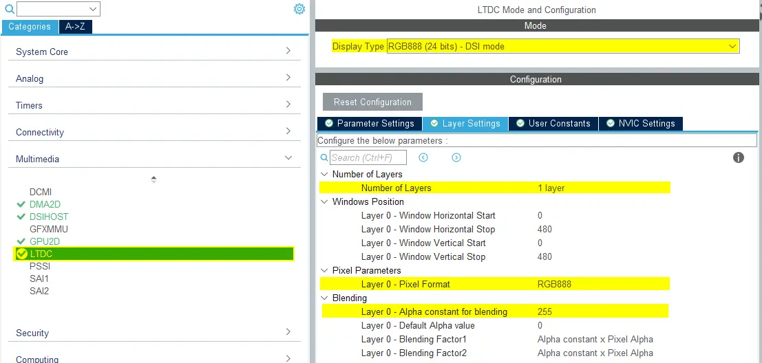
LTDC Configuration
- Set
- NVIC Settings
- Enable LCD-TFT global interrupt
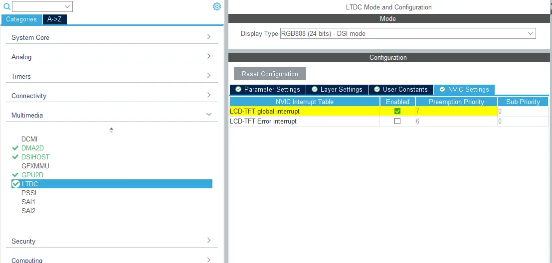
LTDC NVIC Settings
- Enable LCD-TFT global interrupt
DSIHOST Configuration
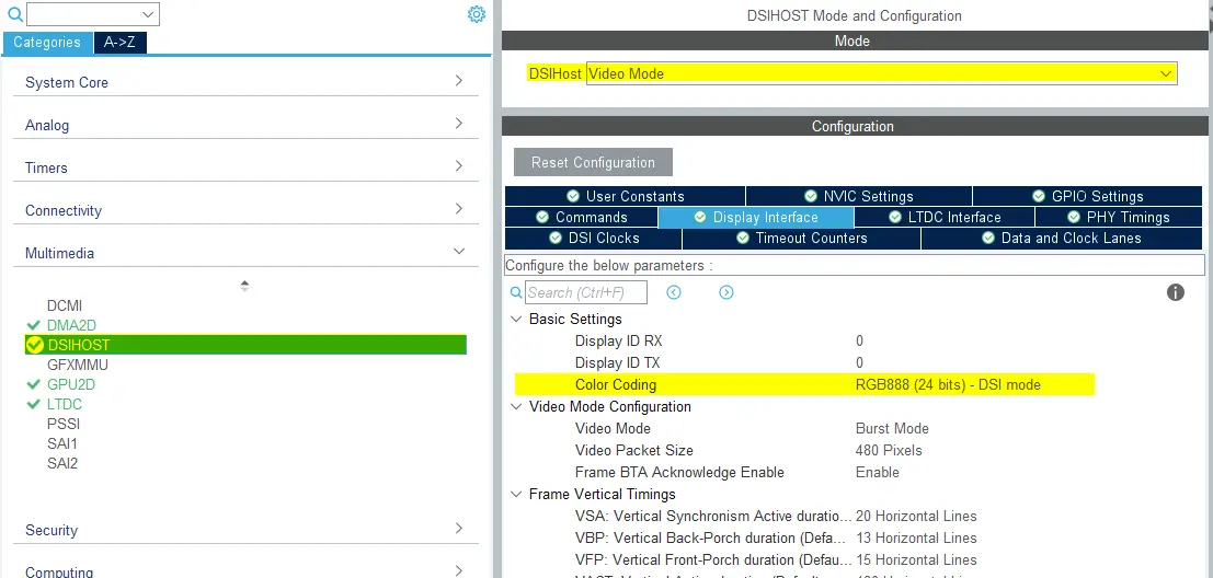
- Mode
- Set
DSIHostto Video Mode
- Set
- Display Interface
- Set
Color Codingto RGB888 (24 bits) - DSI mode - Remaining configurations depends on the selected LCD HW
DSIHOST Configuration
- Set
- NVIC Settings
- DSIHOST global interrupt is not needed and should be disabled.
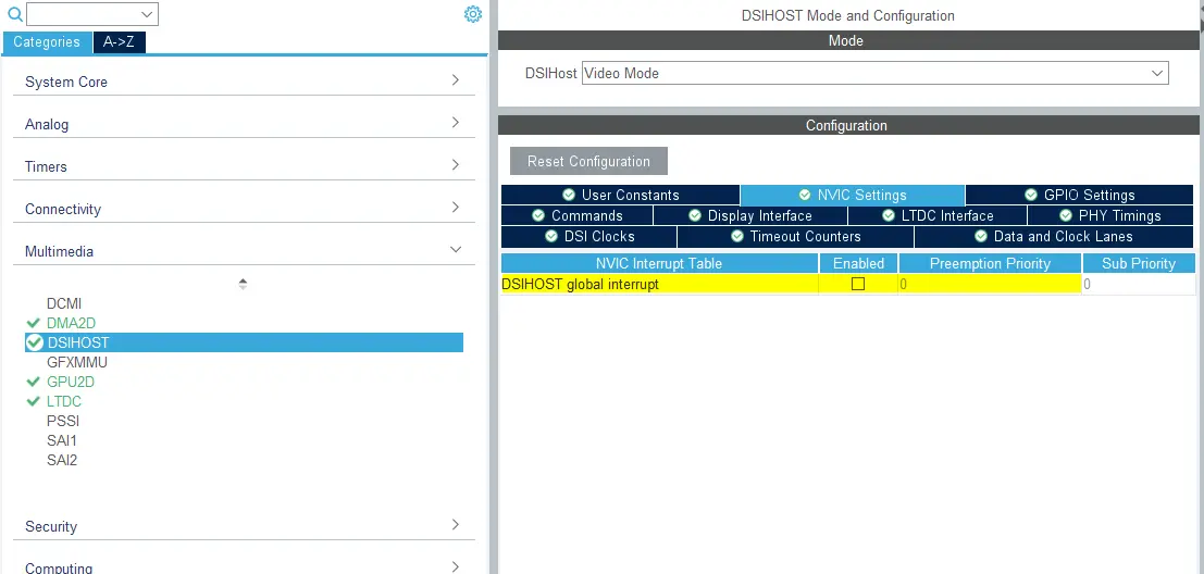
DSIHOST NVIC Settings
- DSIHOST global interrupt is not needed and should be disabled.
TouchGFX Generator
- Mode
- Enable Graphics Application
- TouchGFX Generator
- Set
Display / Interfaceto Parallel RGB (LTDC) since this is still the controller the application needs to communicate with. - Set
Application Tick Sourceto LTDC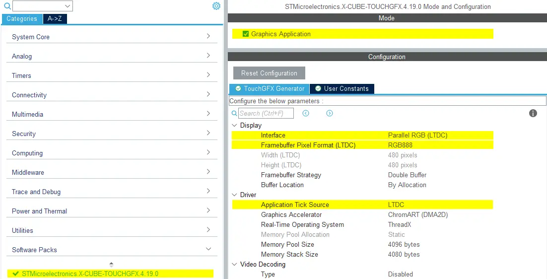
TouchGFX Generator Configuration
- Set
User Code
The TouchGFX Generator can generate a full TouchGFX AL that configures the LTDC to transfer pixels through the DSI Host controller from the framebuffer memory to the display and synchronize the display with the TouchGFX Engine. Only minor adjustments may be required as described below.
DSIHOST / LTDC Initialization sequence
The call to MX_DSIHOST_DSI_Init() must be done before MX_LTDC_Init(). This should be handled by STM32CubeMX.
If this is not correct, take care to fix the order in a user code section.
After calling HAL_DSI_Start(), switch DSIHOST clock to the DSIPHY source:
static void MX_DSIHOST_DSI_Init(void)
{
  ...
  /* Switch to DSI PHY PLL clock */
  RCC_PeriphCLKInitTypeDef PeriphClkInit;
  PeriphClkInit.PeriphClockSelection = RCC_PERIPHCLK_DSI;
  PeriphClkInit.DsiClockSelection    = RCC_DSICLKSOURCE_DSIPHY;
  HAL_RCCEx_PeriphCLKConfig(&PeriphClkInit);
  /* USER CODE END DSIHOST_Init 2 */
  ...
}
User has to add the required initialization code specific to the used LCD controller at the end of the MX_LTDC_Init() function.
That code will be based on the DSI HAL APIs HAL_DSI_ShortWrite() and HAL_DSI_LongWrite():
  static void MX_LTDC_Init(void)
  {
    ...
    /* USER CODE BEGIN LTDC_Init 2 */
    // Specific LCD controller's initialization code
    ...

    // Exit Sleep Mode
    if (HAL_DSI_ShortWrite(&hdsi, 0, DSI_DCS_SHORT_PKT_WRITE_P0, DSI_EXIT_SLEEP_MODE, 0x00) != HAL_OK)
    {
      Error_Handler();
    }

    HAL_Delay(120);
    /* USER CODE END LTDC_Init 2 */
    ...
  }
Updated TouchGFXHAL class for DSI Video Mode
The generated code for the LTDC interrupt is identical to the code generated when using Parallel RGB display interface.
One way to prevent the MIPI DSI display from turning on until we've rendered the first frame in the application is to guard the
function TouchGFXHAL::endFrame to keep the display off until first frame is rendered by TouchGFX. The TouchGFXHAL::endFrame() could be updated as below, to enable the LCD and its Backlight through a HW Timer configured for PWM output.
void TouchGFXHAL::endFrame()
{
    if (!display_on)
    {
        display_on = true;
        /* Enable the LCD, Send Display on DCS command to display */
        HAL_DSI_ShortWrite(&hdsi, 0, DSI_DCS_SHORT_PKT_WRITE_P1, DSI_SET_DISPLAY_ON, 0x00);
        /* Start PWM Timer channel */
        (void)HAL_TIM_PWM_Start(&htim8, TIM_CHANNEL_2);
        /* Enable Backlight by setting Brightness to 100% */
        __HAL_TIM_SET_COMPARE(&htim8, TIM_CHANNEL_2, 2U * 100);
    }

    TouchGFXGeneratedHAL::endFrame();
}
Supported Framebuffer Strategies
- Single
- Double
- Partial - LTDC driven display
Further reading
Reference implementation
The TouchGFX Board Setup STM32U5G9J DK1 includes a reference implementation running DSI Video Mode in RGB888 24-bit framebuffer format.