影像緩衝區
影像緩衝是記憶體的一部分,圖形引擎通過更新影像緩衝,將要在顯示器上顯示的下一幅圖像包含進來。
幀緩衝是RAM的一個連續部分,具有指定大小。

影像緩衝記憶體
影像緩衝具有相應的寬度和高度。 因此,我們通常將影像緩衝視為記憶體的一個二維部分,可通過x、y座標檢索。

二維影像緩衝記憶體
影像緩衝具有相應的色彩格式。 影像緩衝中的每個條目都是該色彩格式下的色彩。 我們將影像緩衝中的每一個這樣的條目稱為像素。
通過計算影像緩衝中像素的儲存位址和更新存儲的色彩,可以更新影像緩衝中位置 x,y 處的像素色彩。
uint32_t pixelAddress = x + y * WIDTH;
framebuffer[ pixelAddress ] = newColor;
同樣地,我們可以獲取影像緩衝中像素的色彩並用在計算中。 例如,暗化影像緩衝中像素的色彩(假設有暗化函數可用)。
uint32_t pixelAddress = x + y * WIDTH;
framebuffer[ pixelAddress ] = darken( framebuffer[ pixelAddress ] );
對於影像緩衝記憶體,通常不會如前文所述逐一讀寫像素,而是利用系統的底層硬體功能(如Chrom-ART DMA)進行讀寫。
顏色
在TouchGFX中,影像緩衝的像素色彩格式可以是:
- 灰度1、2或4位元每像素(bpp)灰度,或者
- 高或真彩16、24或32 bpp色彩
每個像素使用的位元數越多,影像緩衝能夠呈現的顏色就越清晰,此外,每個像素使用的位元數越多,影像緩衝消耗的儲存空間就越多。
Display
影像緩衝的內容最終會被傳輸並顯示在顯示器上。 因此,影像緩衝與顯示器的像素寬度和高度相同是十分常見的。

24 bpp影像緩衝內容和顯示器顯示內容
Further reading
影像緩衝的位置
下面是一個基於微控制器的繪圖系統的簡圖。
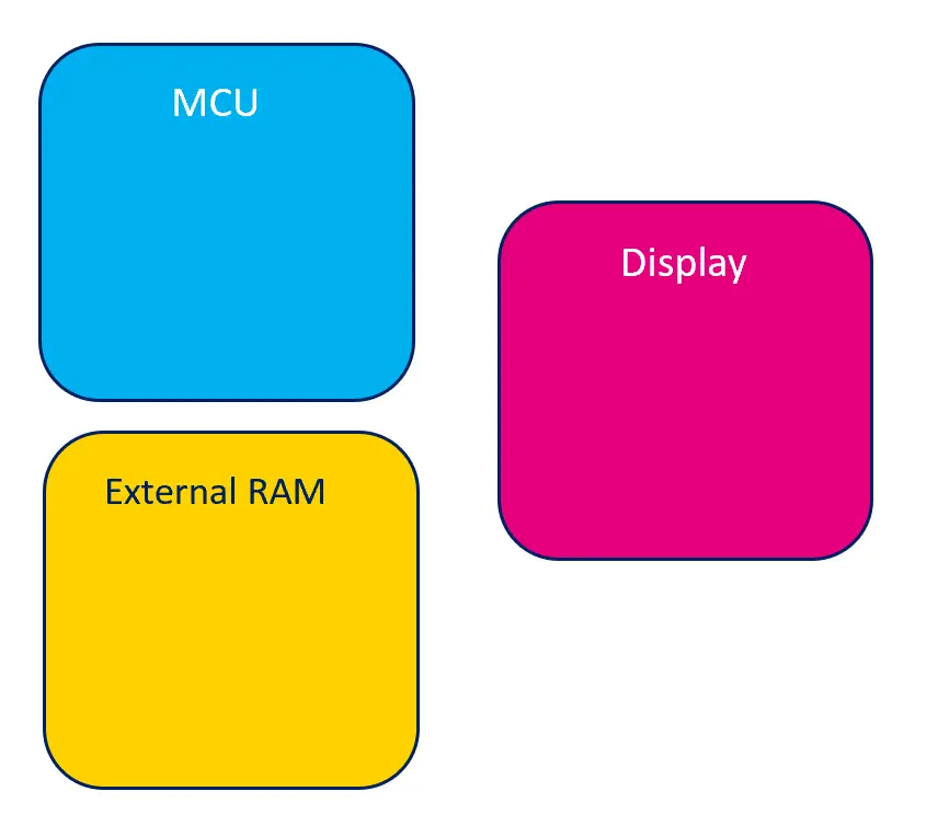
繪圖系統簡圖
影像緩衝可以位於MCU或外部RAM中。
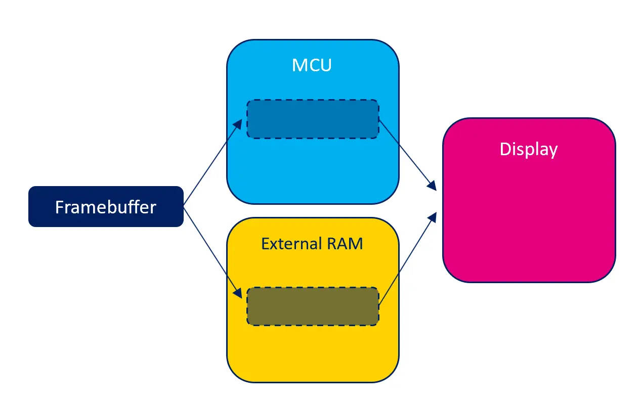
影像緩衝的可能位置
每個可能位置都具有潛在的優勢和不足。
內部RAM
如果影像緩衝位於MCU內部的RAM中,對影像緩衝的讀和寫存取會盡可能快地完成。 這意味著TouchGFX應用的運行會盡可能平穩。 反過來,內部RAM是十分稀少的資源,被系統的許多元件使用,因此,影像緩衝大量佔用內部RAM也不可行。
如果可行,由於無需額外的RAM,在內部RAM中提供影像緩衝可以降低系統的總體成本。
外部RAM
如果系統有外部RAM,可以選擇在外部RAM而不是內部RAM中提供影像緩衝。 對外部RAM的讀和寫存取通常會比內部RAM慢,但外部RAM的空間量通常大得多。 因此,有時候這是唯一可行的解決方案。
MCU可能具有一些功能(如快取記憶體),可加快外部RAM的存取速度。 參見關於MCU的部分瞭解詳細資訊。
含 GRAM 的顯示器
根據系統中的顯示器類型,顯示器上可能會嵌入記憶體 (通常稱為 GRAM)。 此記憶體儲存顯示器“實際”像素的內容。 顯示器中有此像素記憶體,意味著在顯示器仍活動時,MCU可能處於空閒狀態。
由於顯示器記憶體並非記憶體映射,既不打算也不適合用於像素的隨機讀取或寫入,因此不可能在顯示器RAM中提供TouchGFX影像緩衝。 相反,TouchGFX將影像緩衝置於內部或外部RAM中,並在適當的時候將其傳輸到顯示器RAM。
儲存空間消耗
影像緩衝中的色彩數量和像素數量決定了影像緩衝消耗的儲存空間。
影像緩衝使用的儲存空間通常為 寬 高 以位元數計的色深 / 8 位元組數。
| 解析度(像素) | 色彩(bpp) | 計算 | 消耗的儲存空間(位元組) |
|---|---|---|---|
| 800x480 | 16 bpp | 800 480 16 / 8 | 768,000 B |
| 480x272 | 24 bpp | 480 272 24 / 8 | 391,680 B |
| 100x100 | 8 bpp | 100 100 8 / 8 | 10,000 B |
當具有一個以上的影像緩衝時,消耗的存儲空間相對地較大。 例如,當使用雙重影像緩衝方案時,使用兩個影像緩衝會消耗兩倍的儲存空間。
當影像緩衝不足一個時,由應用明確地分配和控制存儲空間的量。 因此,存儲空間的消耗量是完全可定制的,但應注意的是,使用量過少會影響整體圖形性能。
影像緩衝區策略
影像緩衝區策略是一項核心功能,能夠在 TouchGFX 渲染和您現有的硬體 (MCU、RAM 和顯示器) 之間 達到最佳化的配對。 如果您正在挑選新的硬體, 建議從可用的影像緩衝區策略當中, 找出並熟悉與您的使用案例相關的策略。 正確的選擇 可以幫助最佳化您的硬體成本,即幫助您選擇最低硬體要求, 例如影像緩衝區的 RAM 容量 和適當的顯示器介面。
影像緩衝區策略定義用於影像緩衝區的 RAM 大小, 並控制 TouchGFX 如何渲染到 RAM。 策略必須符合 系統中可用的 RAM 和顯示器類型。 TouchGFX 提供三種不同的策略,適用於各種顯示系統, 不論是否具備 GRAM。 以下概述這些策略,並重點強調 與顯示系統相關的優缺點。
不含 GRAM 的顯示器
| 策略 | 優點 | 缺點 | 使用案例 |
|---|---|---|---|
| 雙重 | 無螢幕撕裂風險、渲染時間最佳化 | 2 個影像緩衝區佔用 RAM | 高效能 UI |
| 單一 | 僅 1 個影像緩衝區佔用 RAM | 有螢幕撕裂風險、渲染時間不理想 | 高-中等效能 UI |
| 局部 | 僅使用少於一個影像緩衝區的 RAM | 螢幕撕裂風險更高、CPU 負載更高 | 中等-低效能 UI |
含 GRAM 的顯示器
| 策略 | 優點 | 缺點 | 使用案例 |
|---|---|---|---|
| 雙重 | 無螢幕撕裂風險、渲染時間最佳化 | 2 個影像緩衝區佔用 RAM | 高效能 UI |
| 單一 | 僅 1 個影像緩衝區佔用 RAM、無螢幕撕裂風險 | 渲染時間不理想 | 高-中等效能 UI |
| 局部 | 僅使用少於一個影像緩衝區的 RAM | 螢幕撕裂風險 | 中等-低效能 UI |
螢幕撕裂
螢幕撕裂是顯示器上的一種視覺瑕疵, 其中兩個影格的像素資料顯示在同一個螢幕畫面中, 例如,螢幕畫面一半是舊影格、一半是目前的影格, 具有明顯的水平切割線 (撕裂)。 螢幕撕裂的位置取決於時間, 通常會出現在各處,可能干擾觀賞體驗。
UI 效能
在一般效能一文中, 您將瞭解 UI 效能的各個層面, 包括個別 UI 元件及其結構如何影響效能。 對於我們設想的影像緩衝區策略而言,效能分類如下:
- 高效能-UI 使用多個複雜 UI 元件/動畫,例如紋理映射器、SVG、畫面轉換
- 中等效能-UI 很少使用複雜的 UI 元件/動畫
- 低效能-UI 不使用複雜的 UI 元件/動畫
Note
詞彙表
以下術語用於描述不同的影像緩衝區策略。
- 顯示器控制器 (DC)-從記憶體讀取像素的硬體。 會連續讀取包含像素的記憶體。 有時稱為掃描線。
- 顯示器傳輸 (DT)-負責將像素從影格緩衝記憶體傳輸到 GRAM 的硬體。 僅在需要時由 MCU 啟動。 有時稱為傳輸線。
- 影像緩衝區寫入 (W)-將像素渲染到影像緩衝區的過程。
不含 GRAM 的顯示器
以下展示不含 GRAM 的顯示器的 影像緩衝區運作概念。 所有策略的共同點是 使用顯示器控制器, 直接從影像緩衝區連續讀取像素資料。
雙重緩衝區策略
擁有兩個影像緩衝區可以將下一影格渲染為一個影像緩衝區, 而顯示器控制器會同時掃描另一個影像緩衝區。 下一影格的渲染時間不受顯示器控制器限制。 直到下一個影格準備好之前,影像緩衝區交換被阻止, 亦即不會有螢幕撕裂的風險, 因為顯示器控制器只是再次掃描目前的影像緩衝區。 影像緩衝區 在顯示器控制器掃描完整個影像緩衝區, 並且渲染完成後,才會進行交換。
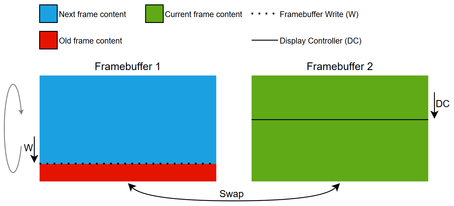
雙重緩衝區策略概念
單一緩衝區策略
擁有一個影像緩衝區,可以將下一影格渲染到 顯示器控制器掃描的相同影像緩衝區。 下一影格的渲染時間 受顯示器控制器限制。 顯示器控制器會連續掃描, 因此如果寫入影像緩衝區的時間太長, 顯示器控制器會碰撞到 (趕上) 寫入區域,並發生螢幕撕裂。 這是由於渲染 複雜的 UI 元件引起。
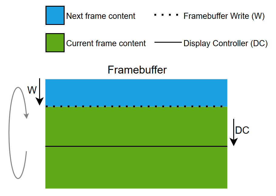
單一緩衝區策略概念
局部緩衝區策略
透過記憶體管理單元 (MMU), 單一局部影像緩衝區塊用於模擬全尺寸影像緩衝區。 因此,這種策略又稱為 模擬影像緩衝區策略。
局部區塊充當滑動視窗, 在模擬影像緩衝區向下移動, 相位和速度是根據顯示器控制器。
局部影像緩衝區塊僅允許渲染下一影格的一小部分, 因為該區塊被重複使用多次 來渲染目前的影格。 局部區塊的重複使用 會導致大量小型渲染運算, 造成更高的 CPU 負載。 下一影格的渲染時間 受顯示器控制器和局部區塊大小限制。 顯示器控制器會連續掃描, 因此如果寫入局部影像緩衝區塊的時間太長 (針對模擬影像緩衝區的任何特定區域), 顯示器控制器會碰撞到 (趕上) 寫入區域, 並發生螢幕撕裂。 這是由於渲染 複雜的 UI 元件引起。 與單一緩衝區策略相比, 螢幕撕裂的風險更高, 因為顯示器控制器的運作區域和影像緩衝區渲染要更小。
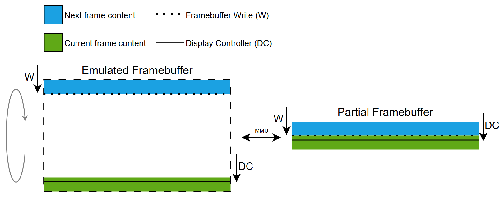
局部緩衝區策略概念
Note
含 GRAM 的顯示器
以下展示 GRAM 顯示器的 影像緩衝區運作概念。 所有策略的共同點,是使用 用於從影像緩衝區傳輸像素資料 到顯示器上的 GRAM 的顯示器介面。
雙重緩衝區策略
擁有兩個影像緩衝區可以將下一影格渲染為一個影像緩衝區, 而像素會同時從另一個緩衝區傳輸到 GRAM。 下一影格的渲染時間 不受顯示器傳輸限制。 直到下一個影格準備好,才會啟動顯示器傳輸, 亦即不會有螢幕撕裂的風險, 因為顯示器控制器只是掃描 GRAM 中已有的內容。 影像緩衝區 在顯示器傳輸和渲染完成後,才會進行交換。
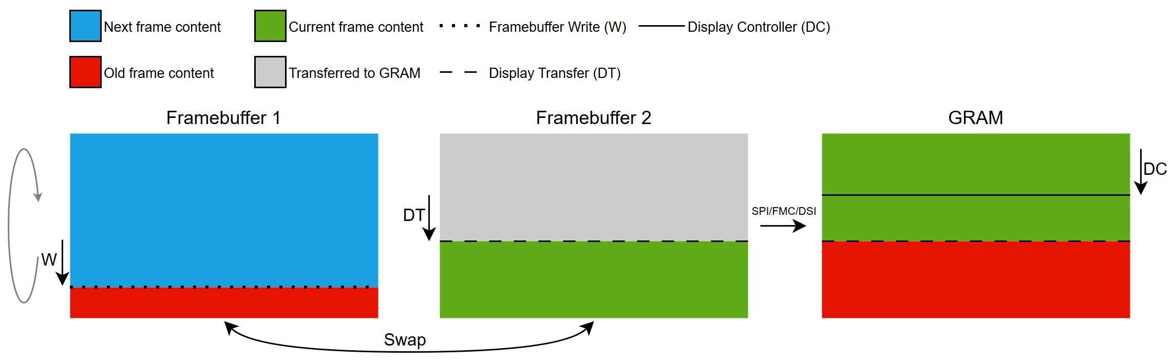
雙重緩衝區策略概念
單一緩衝區策略
擁有一個影像緩衝區,可以將下一影格渲染到 像素被傳送到 GRAM 的相同影像緩衝區。 下一影格的渲染時間 受顯示器傳輸頻寬限制。 直到下一個影格準備好,才會啟動顯示器傳輸, 亦即不會有螢幕撕裂的風險, 因為顯示器控制器只是掃描 GRAM 中已有的內容。 下一影格的渲染在待更新的對應區域 傳輸到 GRAM 之前無法完成。
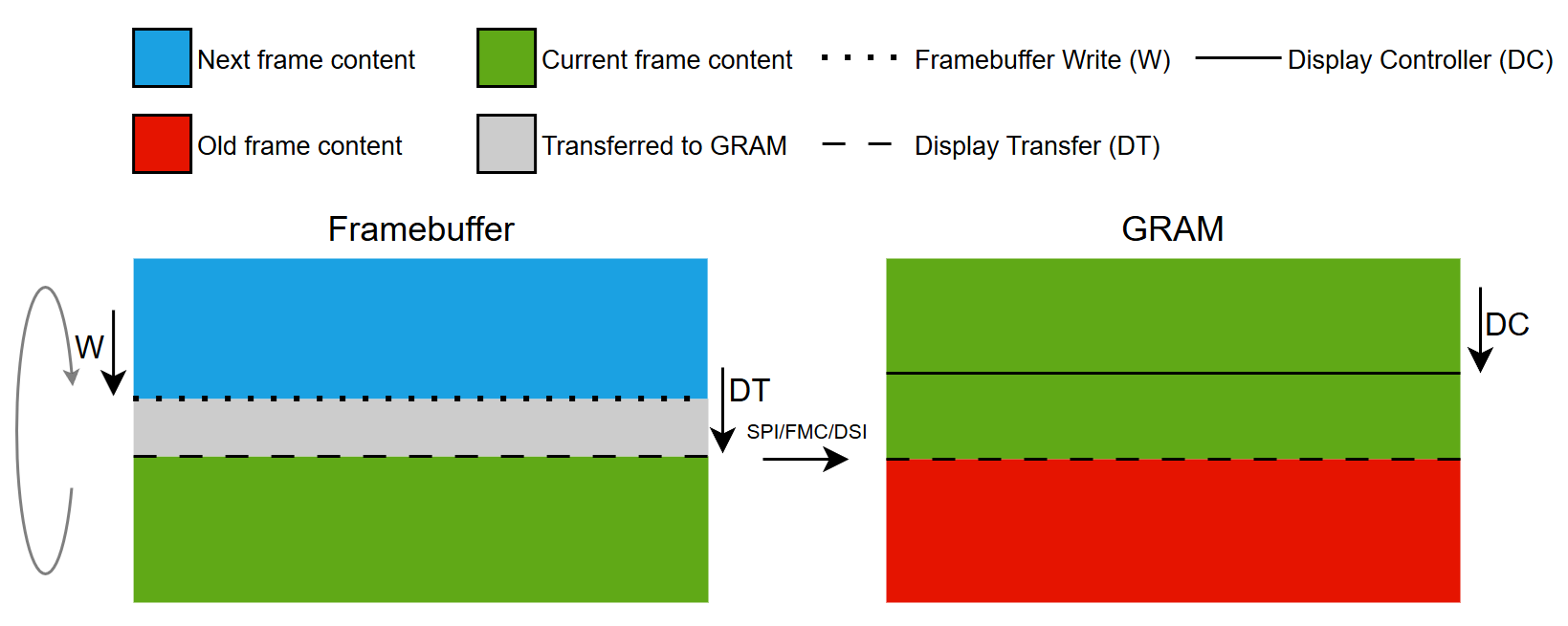
單一緩衝區策略概念
局部緩衝區策略
使用一個或多個局部影像緩衝區塊 來模擬全尺寸影像緩衝區。
局部區塊被重新用於渲染 目前待更新影格的所有部分。 當一個區塊被渲染時,可以 傳輸到 GRAM 並用於後續渲染。
為了盡可能降低螢幕撕裂風險,我們努力 在顯示器傳輸 GRAM 更新和顯示器控制器掃描線之間, 擁有最大的餘裕。 操作方法是讓傳輸線遲於掃描線, 如此一來,我們就只能渲染目前的影格, 而不會開始渲染下一影格。 目前影格的渲染時間 取決於定義的局部區塊數量 及傳輸每個區塊所需的時間。 這表示如有可用的區塊, 我們可以渲染 位於顯示器控制器掃描線前的區塊。 如果渲染和傳輸目前影格的所有「髒區域」 花的時間比顯示器控制器還要長, 其掃描線會包覆並趕上傳輸線,導致螢幕撕裂。 這是由於渲染複雜的 UI 元件 及/或傳輸過多像素引起。
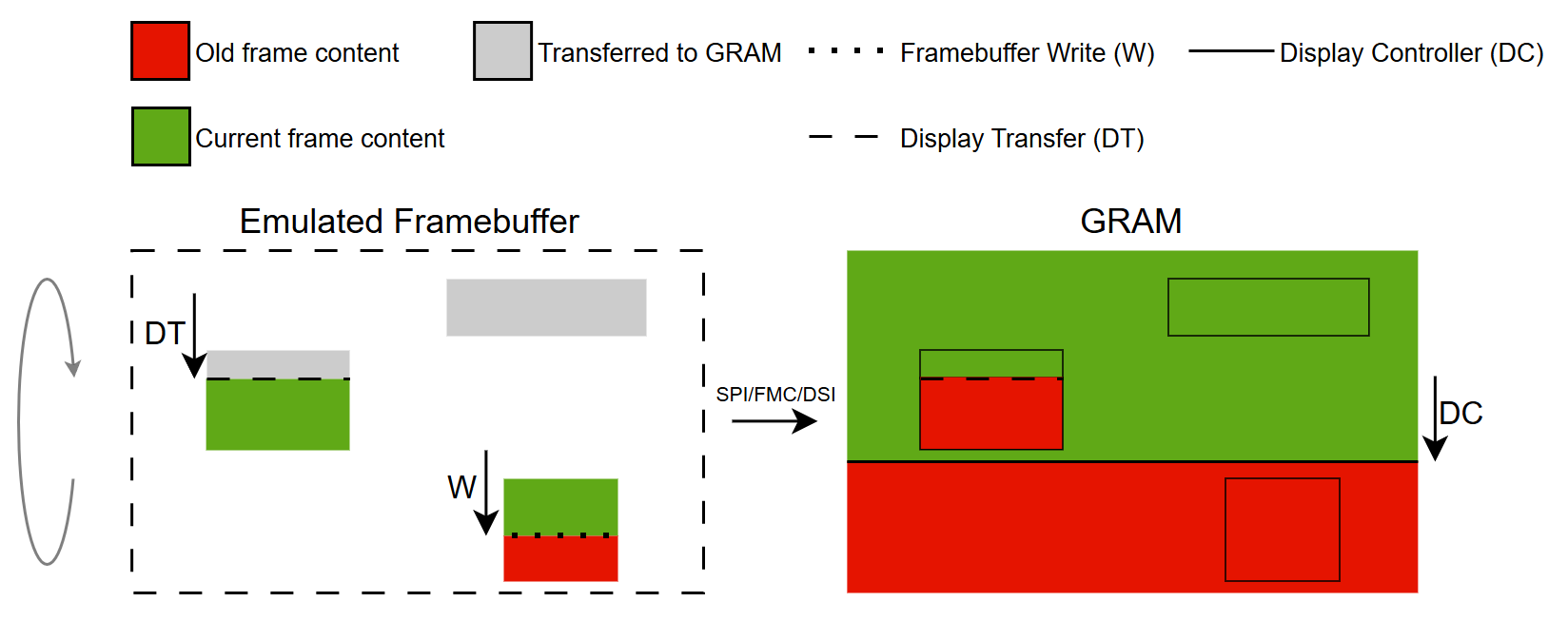
局部緩衝區策略概念
影像緩衝區策略入門
在下一節中,我們將介紹常見的硬體設定, 以及如何在不同硬體設定使用影像緩衝區策略的各種情境。
Further reading
含 GRAM 的顯示器
此顯示器類型具有與顯示器大小相同的專用 RAM 緩衝區,即全尺寸的影像緩衝區。
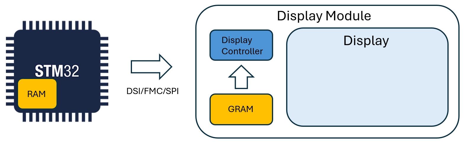
含 GRAM 的顯示器
此類顯示器的介面為:
- FMC
- SPI
- DSI (指令模式)
使用這些介面的情境如下:
不含 GRAM 的顯示器
此顯示器類型沒有專用的 RAM 緩衝區。
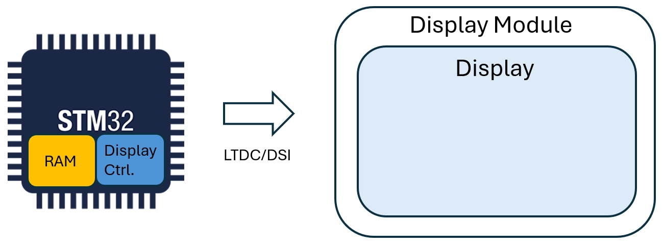
不含 GRAM 的顯示器
此類顯示器的介面為:
- LTDC
- DSI (視訊模式)
使用這些介面的情境如下: