MIPI-DS影片模式
本情境說明如何在使用具有顯示器序列介面 (DSI) 時,設定視訊模式下的 STM32 DSIHOST 以及 TouchGFX Generator。
本文使用的範例適用於 24 位元 RGB888 影像緩衝區格式,並介紹 STM32CubeMX 中的設定,同時以產生的程式碼做示範。
設定
LTDC設定
- 模式
- 將
Display Type設置為RGB888(24位元)-DSI模式
- 將
- 層設置
- 將
Number of layers設置為1 layer - 設置
Layer 0 - Pixel Format設置為RGB888 - 設置
Layer 0 - Alpha constant for blending為255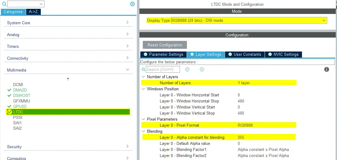
LTDC設定
- 將
- NVIC設定
- 啟用LCD-TFT全域中斷
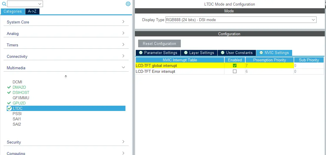
LTDC NVIC 設定
- 啟用LCD-TFT全域中斷
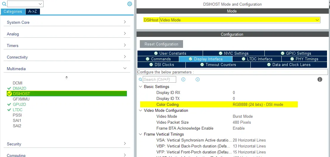
DSIHOST 配置
- 模式
- 將
DSIHost設定為_*Video Mode**
- 將
- 顯示介面
- 將
Color Coding設定為“RGB888(24位元)- DSI模式” - 其餘配置取決於所選的LCD HW
DSIHOST 配置
- 將
- NVIC設定
- DSIHOST無需全域中斷,應禁用。

DSIHOST NVIC 設定
- DSIHOST無需全域中斷,應禁用。
TouchGFX Generator
- 模式
- 啟用Graphics Application
- TouchGFX Generator
- 將
Display / Interface設定為Parallel RGB(LTDC),因為這仍是應用程式與之通信的控制器。 - 將
Application Tick Source設定為LTDC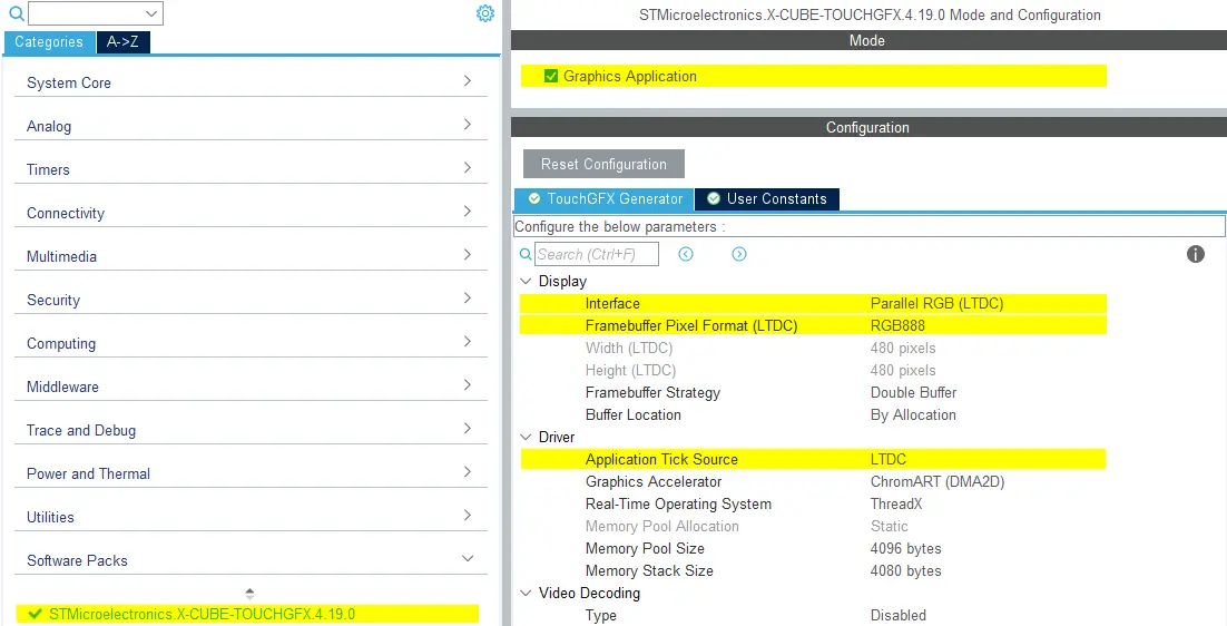
TouchGFXGenerator設定
- 將
使用者程式碼
TouchGFX Generator 可產生全部 TouchGFX AL,其設定 LTDC 透過 DSI 主機控制器將像素從影格緩衝記憶體傳輸到顯示器,並將顯示器與 TouchGFX Engine 同步。 可能只需要微小調整,如下所述。
DSIHOST / LTDC初始化順序
對MX_DSIHOST_DSI_Init()的呼叫必須在MX_LTDC_Init()之前完成。 這應該由 STM32CubeMX 處理。 如果不正確,請注意在使用者程式碼區段中修正順序。
呼叫 HAL_DSI_Start() 後,切換 DSIHOST 時脈至 DSIPHY 來源:
static void MX_DSIHOST_DSI_Init(void)
{
  ...
  /* 切換至 DSI PHY PLL 時鐘 */
  RCC_PeriphCLKInitTypeDef PeriphClkInit;
  PeriphClkInit.PeriphClockSelection = RCC_PERIPHCLK_DSI;
  PeriphClkInit.DsiClockSelection    = RCC_DSICLKSOURCE_DSIPHY;
  HAL_RCCEx_PeriphCLKConfig(&PeriphClkInit);
  /* USER CODE END DSIHOST_Init 2 */
  ...
}
使用者必須在MX_LTDC_Init()函數的尾端添加特定於所用LCD控制器的必要初始化程式碼。 該程式碼將基於 DSI HAL APIs HAL_DSI_ShortWrite() 和 HAL_DSI_LongWrite():
  static void MX_LTDC_Init(void)
  {
    ...
    /* USER CODE BEGIN LTDC_Init 2 */
    // Specific LCD controller's initialization code
    ...

    // 退出睡眠模式
    if (HAL_DSI_ShortWrite(&hdsi, 0, DSI_DCS_SHORT_PKT_WRITE_P0, DSI_EXIT_SLEEP_MODE, 0x00) != HAL_OK)
    {
      Error_Handler();
    }

    HAL_Delay(120);
    /* USER CODE END LTDC_Init 2 */
    ...
  }
更新了DSI影片模式的TouchGFXHAL類
LTDC 中斷的已產生程式碼與使用平行 RGB 顯示器介面時產生的程式碼相同。
為了防止 MIPI DSI 顯示器在我們渲染應用程式的第一個影格之前開啟, 一種方法是保護函數 TouchGFXHAL::endFrame 使顯示器維持關閉,直到 TouchGFX 渲染第一個影格。 TouchGFXHAL::endFrame()可像下面這樣更新,通過配置為PWM輸出的HW計時器啟用LCD及其背光。
void TouchGFXHAL::endFrame()
{
    if (!display_on)
    {
        display_on = true;
        /* Enable the LCD, Send Display on DCS command to display */
        HAL_DSI_ShortWrite(&hdsi, 0, DSI_DCS_SHORT_PKT_WRITE_P1, DSI_SET_DISPLAY_ON, 0x00);
        /* Start PWM Timer channel */
        (void)HAL_TIM_PWM_Start(&htim8, TIM_CHANNEL_2);
        /* Enable Backlight by setting Brightness to 100% */
        __HAL_TIM_SET_COMPARE(&htim8, TIM_CHANNEL_2, 2U * 100);
    }

    TouchGFXGeneratedHAL::endFrame();
}
支援的影像緩衝區策略
- 單一
- 雙重
- 局部-LTDC 驅動顯示器
Further reading
參考實作
TouchGFX 開發板設定 STM32U5G9J DK1 包含以 RGB888 24 位元影格緩衝格式執行 DSI 視訊模式的參考實作。