MIPI-DSIビデオ・モード
このシナリオでは、ディスプレイ・シリアル・インタフェース(DSI)を搭載したディスプレイを使用する場合に、ビデオ・モードのSTM32 DSIHOSTとTouchGFX Generatorを設定する方法について説明します。
この記事で使用する例は、24ビットRGB888のフレームバッファ・フォーマットに対応するものです。STM32CubeMXの設定で実行し、生成済みのコード例を示します。
設定
LTDCの設定
- モード
Display TypeをRGB888 (24 bits) - DSI Modeに設定
- レイヤーの設定
Number of layersを1 layerに設定Layer 0 - Pixel FormatをRGB888に設定Layer 0 - Alpha constant for blendingを255に設定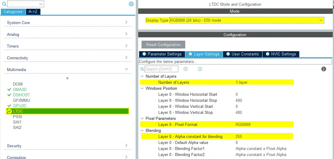
LTDCの設定
- NVICの設定
- LCD-TFT global interruptを有効にする
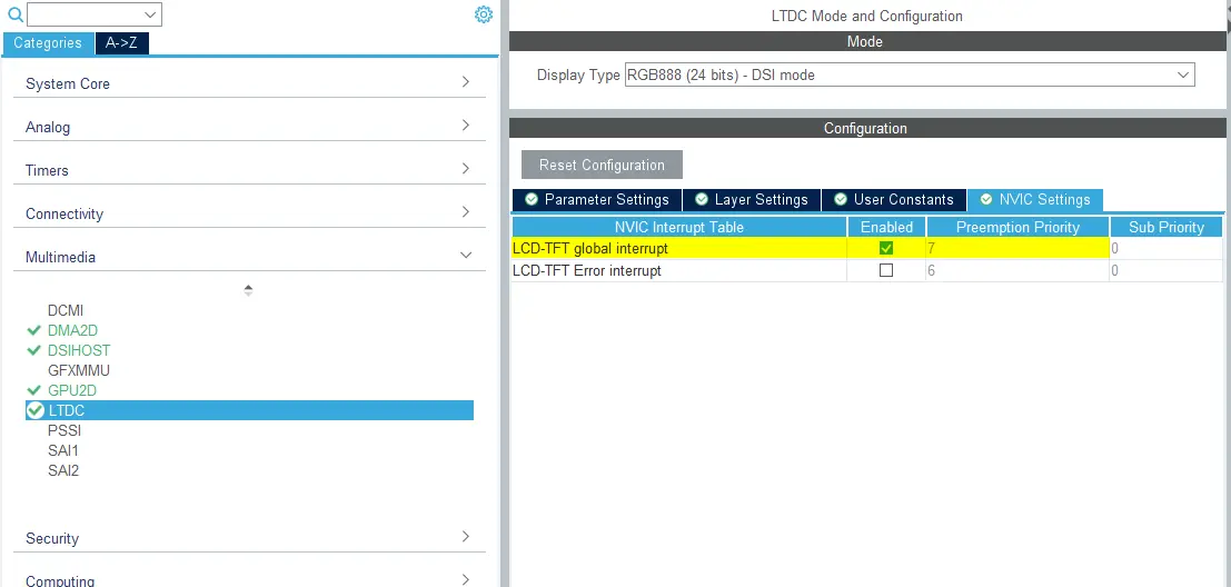
LTDC NVICの設定
- LCD-TFT global interruptを有効にする
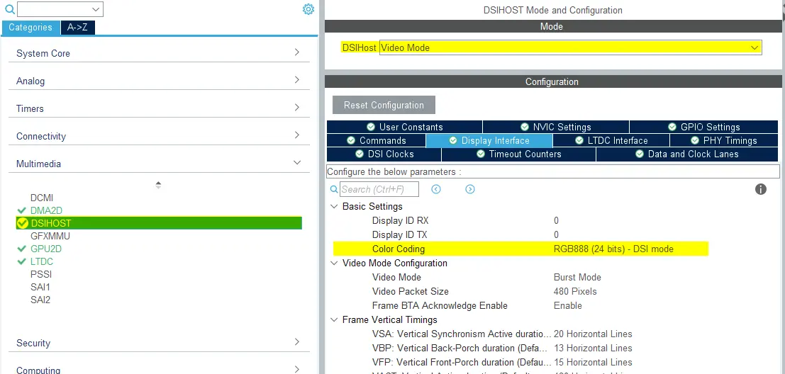
DSIHOSTの設定
- モード
DSIHostをVideo Modeに設定
- ディスプレイ・インタフェース
Color CodingをRGB888 (24 bits) - DSI modeに設定- 残りの設定は選択したLCD HWに応じて異なる
DSIHOSTの設定
- NVICの設定
- DSIHOST global interruptは必要ないので、無効にすること
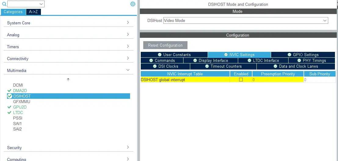
DSIHOST NVICの設定
- DSIHOST global interruptは必要ないので、無効にすること
TouchGFX Generator
- モード
- Graphics Applicationを有効にする
- TouchGFX Generator
Display / InterfaceをParallel RGB (LTDC)に設定(これはコントローラであり、アプリケーションとの通信の必要があるため)Application Tick SourceをLTDCに設定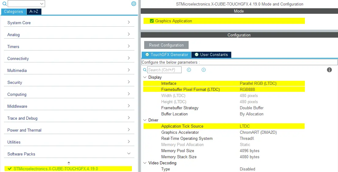
TouchGFX Generatorの設定
ユーザ・コード
TouchGFX Generatorでは完全なTouchGFX ALを生成できます。これは、 DSIホスト・コントローラを介してフレームバッファ・メモリからディスプレイにピクセルを転送し、ディスプレイがTouchGFX Engineと同期するようにLTDCを設定するものです。 以下に示すように、わずかな調整が必要になる場合があります。
DSIHOST / LTDCの初期化シーケンス
MX_DSIHOST_DSI_Init()の呼び出しは、MX_LTDC_Init()の前に行う必要があります。 これはSTM32CubeMXで処理します。 正しくない場合は、ユーザ・コード・セクションで必ず順序を修正してください。
HAL_DSI_Start()の呼び出し後、DSIHOSTクロックをDSIPHYソースに切り替えます。
static void MX_DSIHOST_DSI_Init(void)
{
  ...
  /* Switch to DSI PHY PLL clock */
  RCC_PeriphCLKInitTypeDef PeriphClkInit;
  PeriphClkInit.PeriphClockSelection = RCC_PERIPHCLK_DSI;
  PeriphClkInit.DsiClockSelection    = RCC_DSICLKSOURCE_DSIPHY;
  HAL_RCCEx_PeriphCLKConfig(&PeriphClkInit);
  /* USER CODE END DSIHOST_Init 2 */
  ...
}
ユーザは、MX_LTDC_Init()関数の末尾に、使用されたLCDコントローラに固有の必要な初期化コードを追加する必要があります。 そのコードは、DSI HAL APIのHAL_DSI_ShortWrite()とHAL_DSI_LongWrite()に基づくものになります。
  static void MX_LTDC_Init(void)
  {
    ...
    /* USER CODE BEGIN LTDC_Init 2 */
    // Specific LCD controller's initialization code
    ...

    // Exit Sleep Mode
    if (HAL_DSI_ShortWrite(&hdsi, 0, DSI_DCS_SHORT_PKT_WRITE_P0, DSI_EXIT_SLEEP_MODE, 0x00) != HAL_OK)
    {
      Error_Handler();
    }

    HAL_Delay(120);
    /* USER CODE END LTDC_Init 2 */
    ...
  }
DSIビデオ・モード用に更新されたTouchGFXHALクラス
LTDC割り込み用に生成されるコードは、パラレルRGBディスプレイ・インタフェースの使用時に生成されるコードと同じです。
アプリケーションで最初のフレームの描画を完了するまでMIPI DSIディスプレイがオンになるのを防ぐ1つの方法は、関数TouchGFXHAL::endFrameをガードして、TouchGFXが最初のフレームを描画するまでディスプレイをオフにしておくことです。 TouchGFXHAL::endFrame()を以下のように更新すると、PWM出力用に設定されたHWタイマを通して、LCDとそのバックライトを有効にできます。
void TouchGFXHAL::endFrame()
{
    if (!display_on)
    {
        display_on = true;
        /* Enable the LCD, Send Display on DCS command to display */
        HAL_DSI_ShortWrite(&hdsi, 0, DSI_DCS_SHORT_PKT_WRITE_P1, DSI_SET_DISPLAY_ON, 0x00);
        /* Start PWM Timer channel */
        (void)HAL_TIM_PWM_Start(&htim8, TIM_CHANNEL_2);
        /* Enable Backlight by setting Brightness to 100% */
        __HAL_TIM_SET_COMPARE(&htim8, TIM_CHANNEL_2, 2U * 100);
    }

    TouchGFXGeneratedHAL::endFrame();
}
サポートされるフレームバッファ戦略
- シングル
- ダブル
- パーシャル - LTDC駆動ディスプレイ
Further reading
リファレンス実装
TouchGFXBoard Setup STM32U5G9J DK1には、24ビットRGB888のフレームバッファ・フォーマットでDSIビデオ・モードを実行するリファレンス実装が含まれています。