帧缓冲区
帧缓冲是存储器的一部分,图形引擎通过更新帧缓冲,将需要显示的下一帧图像包含进来。
帧缓冲是RAM的一个连续部分,可以根据需要设定合适的大小。

帧缓存空间
帧缓冲具有相应的宽度和高度。 因此,我们通常将帧缓冲视为存储器的一个二维部分,可通过x、y坐标检索。

2D帧缓存空间
帧缓冲具有相应的色彩格式。 帧缓冲中的每个条目都是该色彩格式下的色彩。 我们将帧缓冲中的每一个这样的条目称为像素。
通过计算帧缓冲中像素的存储地址和更新存储的色彩,可以更新帧缓冲中位置 x,y 处的像素色彩。
uint32_t pixelAddress = x + y * WIDTH;
framebuffer[ pixelAddress ] = newColor;
同样地,我们可以获取帧缓冲中像素的色彩并用在计算中。 例如,暗化帧缓冲中像素的色彩(假设有暗化函数可用)。
uint32_t pixelAddress = x + y * WIDTH;
framebuffer[ pixelAddress ] = darken( framebuffer[ pixelAddress ] );
对于帧缓冲存储器,通常不会如前文所述逐一读写像素,而是利用系统的底层硬件功能(如Chrom-ART DMA)进行读写。
色彩
在TouchGFX中,帧缓冲的像素色彩格式可以是:
- 灰度1、2或4位每像素(bpp)灰度,或者
- 高或真彩16、24或32 bpp色彩
每个像素使用的位数越多,帧缓冲能够呈现的颜色就越清晰,此外,每个像素使用的位数越多,帧缓冲消耗的存储空间就越多。
显示屏
帧缓冲的内容最终会被传输到并显示在物理显示屏上。 因此,帧缓冲与显示屏的像素宽度和高度相同是十分常见的。

24 bpp帧缓冲内容和显示屏显示内容
Further reading
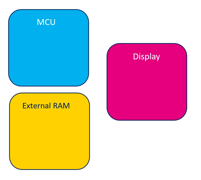
帧缓冲的位置
下面是一个基于微控制器的绘图系统的极简图。
绘图系统极简图
帧缓冲可以位于MCU内部或外部RAM中。
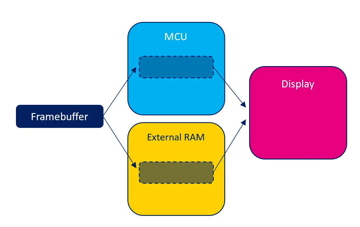
帧缓冲的可能位置
每个可能位置都具有潜在的优势和不足。
内部RAM
如果帧缓冲位于MCU内部的RAM中,对帧缓冲的读和写访问会尽可能快地完成。 这意味着TouchGFX应用的运行会非常流畅。 反过来,内部RAM是十分稀少的资源,被系统的许多部件使用,因此,帧缓冲大量占用内部RAM也许不可行。
如果可行,由于无需额外的RAM,在内部RAM中提供帧缓冲可以降低系统的总体成本。
外部RAM
如果系统有外部RAM,可以选择在外部RAM而不是内部RAM中提供帧缓冲。 对外部RAM的读和写访问通常会比内部RAM慢,但外部RAM的空间量通常大得多。 因此,有时候这是唯一可行的解决方案。
MCU可能具有一些功能(如缓存),可加快外部RAM的访问速度。 参见关于MCU的部分了解详细信息。
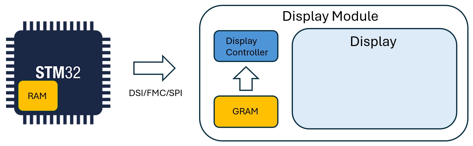
带GRAM的显示屏
根据系统中显示屏的类型不同,显示屏可能内置存储器(通常称为GRAM)。 这段存储空间用来保存显示屏“实际”像素的内容。 显示屏中保存像素的存储空间,意味着在显示屏仍活动时,MCU可能处于空闲状态。
由于显示屏存储器并非存储器映射,既不打算也不适合用于像素的随机读取或写入,因此不可能将TouchGFX帧缓冲放在在显示屏自带的RAM中。 相反,TouchGFX将帧缓冲置于内部或外部RAM中,并在适当的时候将其传输到显示屏RAM。
存储空间消耗
帧缓冲中的色彩数量和像素数量决定了帧缓冲消耗的存储空间。
帧缓冲使用的存储空间通常为 宽 * 高 * 以位数计的色深 / 8 字节数。
| 分辨率(像素) | 色彩(bpp) | 计算 | 消耗的存储空间(字节) |
|---|---|---|---|
| 800x480 | 16 bpp | 800 * 480 * 16 / 8 | 768,000 B |
| 480x272 | 24 bpp | 480 * 272 * 24 / 8 | 391,680 B |
| 100x100 | 8 bpp | 100 * 100 * 8 / 8 | 10,000 B |
当具有一个以上的帧缓冲时,消耗的存储空间相应地较大。 例如,当使用双重缓冲方案时,使用两个帧缓冲会消耗两倍的存储空间。
当帧缓冲不足一个时,由应用明确地分配和控制存储空间的量。 因此,存储空间的消耗量是完全可定制的,但应注意的是,使用量过少会影响整体图形性能。
帧缓存策略
帧缓存策略是一项核心功能,可使TouchGFX渲染与现有硬件(MCU、RAM和显示屏)之间实现最优匹配。 若需选择新硬件,建议先熟悉与您用例相关的可用 帧缓存策略。 正确选择可优化硬件成本,即在帧缓存所需的RAM容量和合适的显示接口方面,协助选择最低硬件配置。
帧缓存策略定义了用于帧缓存的RAM容量,并控制TouchGFX如何渲染至RAM。 该策略必须与系统中的可用RAM及显示屏类型相匹配。 TouchGFX提供三种不同策略,适用于带GRAM 和无GRAM的显示系统。 下方是对各策略的概述,重点分析每个策略在显示系统中的优点和缺点。
无GRAM的显示屏
| 策略 | 优点 | 缺点 | 应用案例 |
|---|---|---|---|
| 双帧缓存 | 无撕裂风险、渲染时间最优 | 需要存放双帧缓存的RAM | 高性能UI |
| 单帧缓存 | 只需单帧缓存的RAM | 存在撕裂风险、渲染时间次优 | 中高性能UI |
| 部分缓存 | 所需RAM少于单帧缓冲 | 撕裂风险更高、CPU负载更大 | 中低性能UI |
具有GRAM的显示屏
| 策略 | 优点 | 缺点 | 应用案例 |
|---|---|---|---|
| 双帧缓存 | 无撕裂风险、渲染时间最优 | 需要存放双帧缓存的RAM | 高性能UI |
| 单帧缓存 | 仅需单帧缓冲RAM、无撕裂风险 | 渲染时间次优 | 中高性能UI |
| 部分缓存 | 所需RAM少于单帧缓冲 | 存在撕裂风险 | 中低性能UI |
画面撕裂
画面撕裂 (Tearing) 指显示屏上的视觉伪影,即单次屏幕刷新时同时显示两帧画面的像素数据。例如:屏幕上半部分显示旧帧内容,下半部分显示当前帧内容,两者之间出现明显的水平分裂线(即撕裂线)。 撕裂线的位置会随刷新时序变化而动态移动,影响视觉观感。
UI性能
在通用性能文章中,您将了解UI性能的相关内容,包括单个UI组件及其结构如何影响性能。 在帧缓存策略的上下文中,我们对性能的定义如下:
- 高性能:使用多个复杂UI组件/动画的UI,例如纹理映射 (Texture Mappers)、SVG以及屏幕过渡动画。
- 中等性能:使用少量复杂UI组件/动画的UI。
- 低性能:不使用任何复杂UI组件/动画的UI。
Note
词汇表
下列术语用于描述不同的帧缓存策略。
- 显示控制器 (DC) - 持续从内存读取 像素数据的硬件设备。 有时也称作扫描行。
- 显示传输 (DT) - 负责将像素从帧缓存内存传输到GRAM的硬件。 该传输仅由MCU在需要时启动。 有时也称作传输行。
- 帧缓存写入 (W) - 将像素渲染到帧缓存的过程。
无GRAM的显示屏
以下内容阐述无GRAM显示屏上各种帧缓存策略的工作原理。 所有策略的共性在于使用显示控制器直接从帧缓存中持续读取像素数据。
双缓存策略
采用双帧缓存配置,当显示控制器扫描其中一个帧缓存时,系统可同时将下一帧渲染至另一个帧缓存。 下一帧的渲染时间不受显示控制器限制。 帧缓存切换会被阻塞,直至下一帧准备就绪,这意味着显示控制器只是重新扫描当前帧缓存,从而避免了画面撕裂的风险。 只有当显示控制器完成整个帧缓存的扫描且渲染完成后,才会进行帧缓存的交换操作。
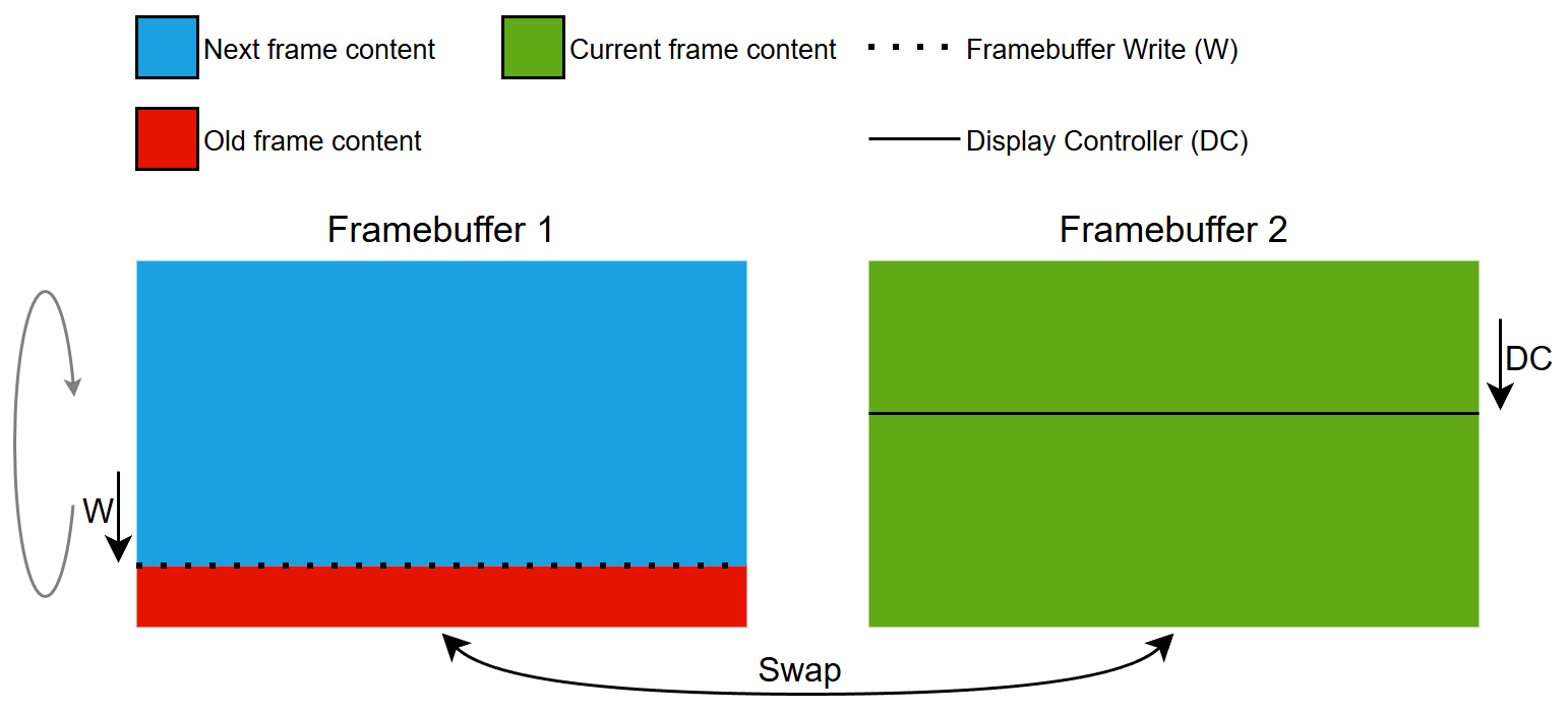
双缓存策略原理
单缓存策略
使用单帧缓存时,可将下一帧渲染至显示控制器正在扫描的同一帧缓存中。 下一帧的渲染时间受显示控制器的限制。 显示控制器持续扫描,若帧缓存写入耗时过长, 显示控制器的扫描进度会与写入区域发生冲突(即“追上”写入位置),从而导致画面撕裂。 这种情况通常由渲染复杂UI组件引起。
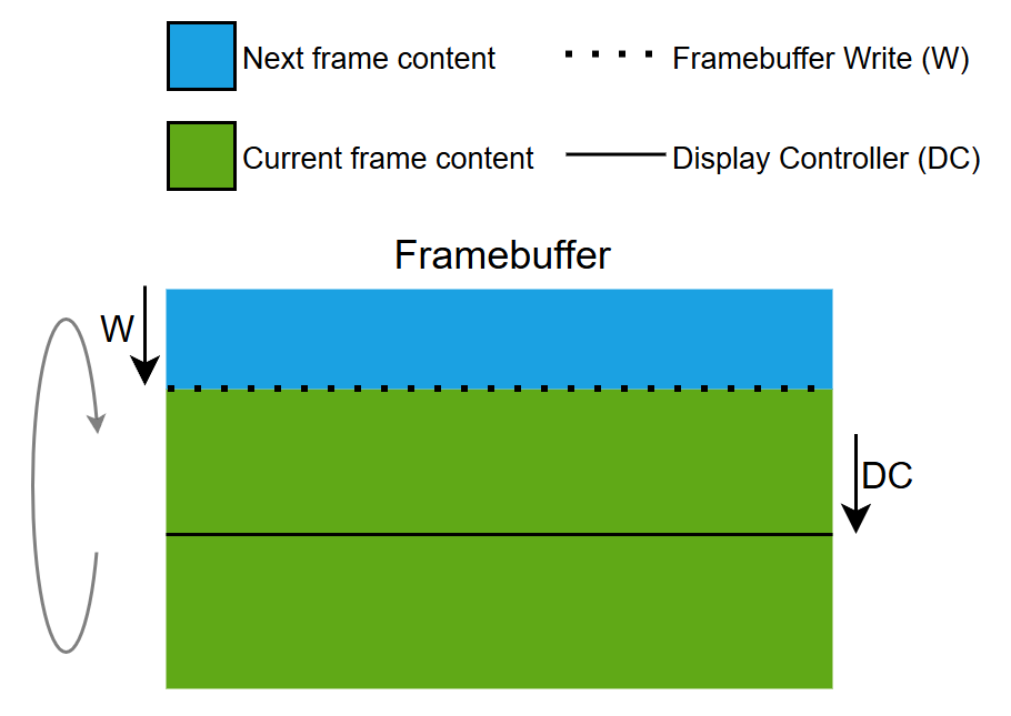
单缓存策略原理
部分缓存策略
通过内存管理单元 (MMU),单个部分帧缓存块可 模拟全尺寸的帧缓存。 因此,该策略也被称作模拟帧缓存策略。
该部分区块作为滑动窗口,以显示控制器的相位和速度在模拟帧缓存中向下移动。
由于部分帧缓存块需要被重复使用来渲染当前帧,因此每次只能渲染下一帧的局部区域。 部分区块的重复使用会导致大量小型渲染操作,从而增加CPU负载。 下一帧的渲染时间同时受显示控制器和部分缓存块尺寸的限制。 显示控制器持续进行扫描,如果在模拟帧缓存的任何区域对部分帧缓存块的写入耗时过长,显示控制器的扫描进度将与写入区域发生冲突(即“追上”写入位置),导致画面撕裂。 这种情况通常由渲染复杂UI组件引起。 与单缓存策略相比,由于显示控制器工作区域和帧缓存渲染区域更小,本策略出现画面撕裂的风险更高。

部分缓存策略原理
Note
具有GRAM的显示屏
以下内容阐述带GRAM显示屏上各种帧缓存策略的工作原理。 所有策略的共同点在于使用显示接口将像素数据从帧缓存传输至显示屏的GRAM中。
双缓存策略
采用双帧缓存配置,当像素数据从一个帧缓存传输至GRAM时,系统可同时将下一帧渲染至另一个帧缓存。 下一帧的渲染时间不受显示传输的限制。 只有当下一帧准备就绪时才会启动显示传输,这意味着不存在撕裂风险,因为显示控制器仅扫描GRAM中已有的数据。 帧缓存会在完成显示传输和渲染后进行交换。
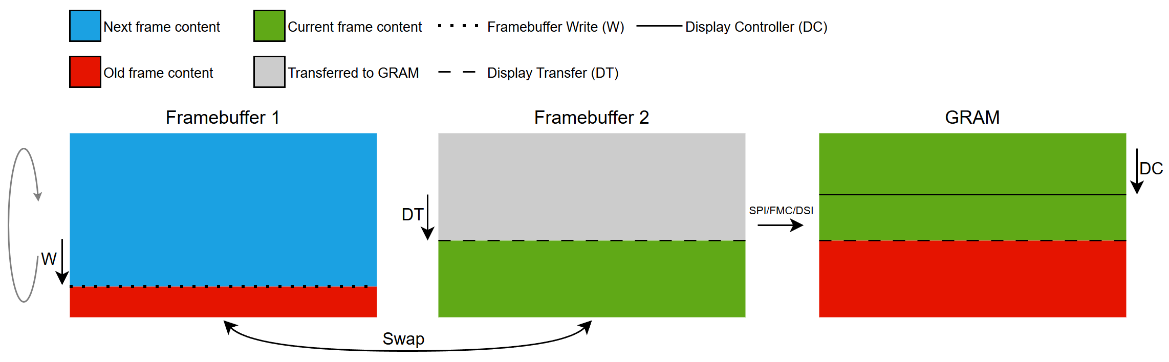
双缓存策略原理
单缓存策略
使用单帧缓存,系统可实时向GRAM传输像素数据的同时,将下一帧画面渲染到同一个帧缓存中。 下一帧的渲染时间受显示传输带宽限制。 只有当下一帧准备就绪时才会启动显示传输,这意味着不存在撕裂风险,因为显示控制器仅扫描GRAM中已有的数据。 在待更新区域完成GRAM传输前,无法完成下一帧的渲染。
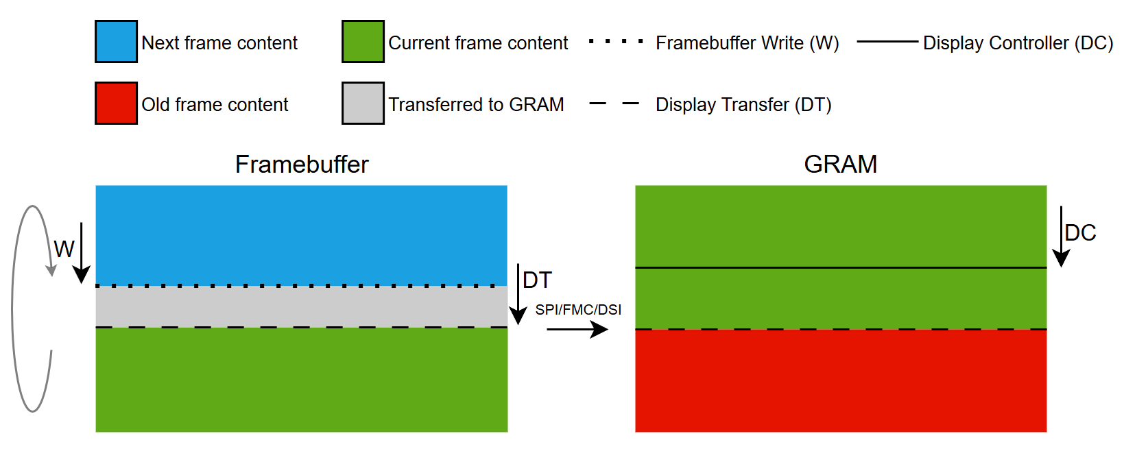
单缓存策略原理
部分缓存策略
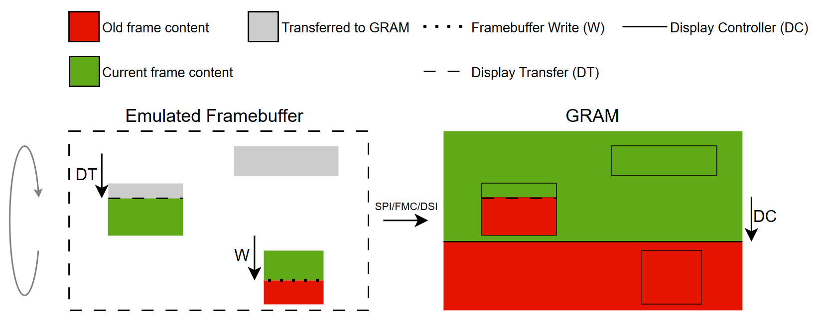
本策略通过使用一个或多个部分帧缓存块来模拟全尺寸的帧缓存。
部分区块会被复用,以渲染当前帧中所有需更新的部分。 区块渲染完成后可传输至GRAM,供后续渲染使用。
为最小化画面撕裂风险,我们力求在显示传输更新GRAM与显示控制器扫描行之间保持最大间距。 具体实现方式是让传输行位于扫描行后方,这意味着系统只能渲染当前帧,而无法开始下一帧的渲染。 当前帧的渲染时间取决于定义的部分区块数量及每个区块的传输耗时。 在此机制下,当区块可用时,系统可以渲染显示控制器扫描行前方的区块。 如果当前帧所有需要更新区域的渲染和传输耗时超过显示控制器的扫描周期,扫描行可能回绕并追上传输行,从而导致画面撕裂。 这种情况通常由于渲染复杂的UI组件和/或传输过多像素数据所导致。
部分缓存策略原理
帧缓存策略入门指南
本节将展示常见硬件配置方案,并说明如何在不同硬件环境中应用帧缓存策略。
Further reading
具有GRAM的显示屏
此类显示屏配备与显示区域大小相同的专用RAM缓存(即全尺寸帧缓存)
带GRAM的显示屏
支持的接口包括:
- FMC
- SPI
- DSI(命令模式)
相关接口应用场景示例:
无GRAM的显示屏
此类显示屏不配备专用RAM缓存。
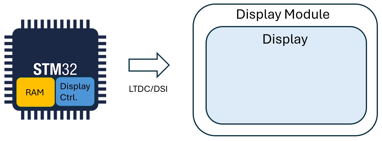
无GRAM的显示屏
支持的接口包括:
- LTDC
- DSI(视频模式)
相关接口应用场景示例: