Framebuffer
A framebuffer is a piece of memory that is updated by the graphics engine to contain the next image to be shown on the display.
The framebuffer is a contiguous part of RAM of a given size.

Framebuffer memory
A framebuffer has an associated width and height. Therefore we typically think of a framebuffer as being a two dimensional part of memory, indexable by x, y coordinates.

2D framebuffer memory
A framebuffer has an associated color format. Each entry in the framebuffer will be a color in this color format. We will refer to each such entry in the framebuffer as a pixel.
We can update the color of a pixel at position x,y in the framebuffer by calculating the memory address of the pixel within the framebuffer and updating the stored color.
uint32_t pixelAddress = x + y * WIDTH;
framebuffer[ pixelAddress ] = newColor;
Similarly we can obtain the color of a pixel in the framebuffer and use this in calculations. For instance darkening the color
of a pixel in the framebuffer (assuming we have a darken function available).
uint32_t pixelAddress = x + y * WIDTH;
framebuffer[ pixelAddress ] = darken( framebuffer[ pixelAddress ] );
Often the framebuffer memory is not written and read pixel by pixel as above, but by utilizing the underlying hardware capabilities of the system, e.g. the Chrom-ART DMA.
Colors
In TouchGFX the pixel color format of a framebuffer can be either:
- Grayscale 1, 2 or 4 bits per pixel (bpp) grayscale, or
- High or true color 16, 24 or 32 bpp color
The more bits per pixels used the more distinct colors can be represented by the framebuffer, moreover the more bits per pixels used the more memory will be consumed by the framebuffer.
Display
The contents of the framebuffer is what is ultimately transferred to and seen on the physical display. Therefore it is very common to have the same pixel width and height of the framebuffer and the display.

24 bpp framebuffer contents and resulting display
Further reading
Location of framebuffer
One oversimplified view of a microcontroller based graphics system is here.
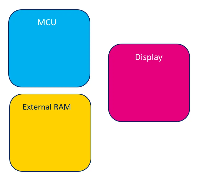
Oversimplified view of graphics system
A framebuffer can be placed either internally in the MCU or in external RAM.
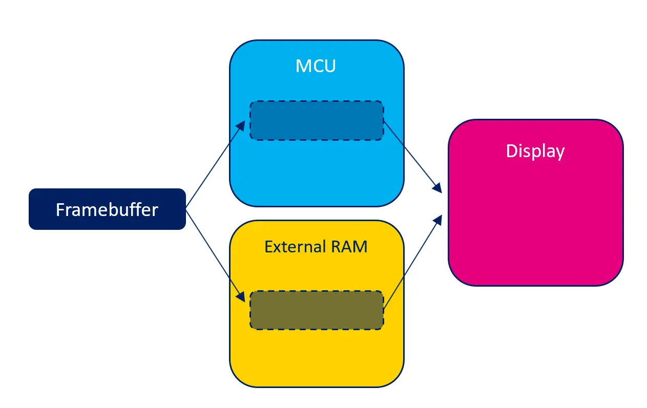
Possible locations of framebuffer
Each possible location has potential benefits and drawbacks.
Internal RAM
Placing the framebuffer in RAM internal to the MCU makes the read and write access to the framebuffer as fast as possible. This means that your TouchGFX application will run as smooth as possible. Conversely, internal RAM is a very scarce resource and one that is used by many parts of a system, therefore occupying a large part of this with a framebuffer might be infeasible.
If feasible, having a framebuffer in internal RAM, could reduce the overall cost of the system as no additional RAM is needed.
External RAM
If the system has external RAM, placing the framebuffer here is an alternative to placing it in internal RAM. The read and write access to external RAM will typically be slower than to the internal RAM, but the amount of external RAM will typically be much larger. Therefore this is sometimes the only viable solution.
The MCU might have capabilities, like caching, that makes access to external RAM faster. See the section on MCU for details.
Display with GRAM
Depending on the type of display in the system there might be memory embedded on the display (often called GRAM). This memory holds the contents of the "physical" pixels of the display. Having this pixel memory in the display implies that the MCU can be idle while the display is still alive.
Placing a TouchGFX framebuffer in the RAM of the display is not possible, as the memory of the display is not memory mapped and is not intended nor suitable for random pixel reads or writes. Instead TouchGFX places the framebuffer in internal or external RAM and transfers this to the display RAM when appropriate.
Memory consumption
The amount of colors and the number of pixels in the framebuffer determines the memory consumed by the framebuffer.
In general the amount of memory used by a framebuffer is width * height * color depth in bits / 8 bytes.
| Resolution (pixels) | Colors (bpp) | Calculation | Memory consumed (byte) |
|---|---|---|---|
| 800x480 | 16 bpp | 800 * 480 * 16 / 8 | 768,000 B |
| 480x272 | 24 bpp | 480 * 272 * 24 / 8 | 391,680 B |
| 100x100 | 8 bpp | 100 * 100 * 8 / 8 | 10,000 B |
When having more than one framebuffer the amount of memory consumed will be correspondingly larger. For example when having a double buffering scheme, using two framebuffers, will consume twice the amount of memory.
When having less than one framebuffer the amount of memory is explicitly allocated and controlled by the application. The memory consumption is therefore completely customizable, but be warned that using too little will harm the overall graphics performance.
Framebuffer Strategies
Framebuffer strategy is a core feature, that enables you to make the most optimal match between TouchGFX rendering and your existing hardware (MCU, RAM and Display). In case you are selecting new hardware, it is recommended to get familiar with the available framebuffer strategies in relation to your use case. The right choice can help optimize your hardware cost, i.e. assist you in selecting the minimum required hardware in terms of the amount of RAM for framebuffer(s) and the suitable display interface.
A framebuffer strategy defines how much RAM is used for framebuffers and controls how TouchGFX renders to the RAM. The strategy must match the available RAM and the type of display in the system. TouchGFX offers three different strategies, applicable on display systems with and without GRAM. Below is an overview of the strategies, highlighting their advantages and drawbacks in relation to display systems.
Displays without GRAM
| Strategy | Advantages | Drawbacks | Use Cases |
|---|---|---|---|
| Double | No risk of tearing, optimal time for rendering | RAM for 2 framebuffers | High performance UIs |
| Single | Only RAM for 1 framebuffer | Risk of tearing, suboptimal time for rendering | High - Moderate performance UIs |
| Partial | Only RAM for less than a framebuffer | Higher risk of tearing, higher CPU load | Moderate - Low performance UIs |
Displays with GRAM
| Strategy | Advantages | Drawbacks | Use Cases |
|---|---|---|---|
| Double | No risk of tearing, optimal time for rendering | RAM for 2 framebuffers | High performance UIs |
| Single | Only RAM for 1 framebuffer, no risk of tearing | Suboptimal time for rendering | High - Moderate performance UIs |
| Partial | Only RAM for less than a framebuffer | Risk of tearing | Moderate - Low performance UIs |
Tearing
Tearing is a visual artifact on the display where pixel data from two frames are shown in one screen draw, e.g. the screen has half of an old frame and half of a current one, with a clean horizontal split across (the tear). The location of the tear varies according to timing, it usually jumps all over the place, which can be distracting.
UI Performance
In the general Performance article, you will be introduced to aspects of UI performance, which covers how the individual UI components and there structure impacts performance. In the context of framebuffer strategy we think of:
- High performance, as UIs that uses multiple complex UI components/animations, e.g. Texture Mappers, SVGs, screen transitions
- Moderate performance, as UIs that uses few complex UI components/animations
- Low performance, as UIs that uses no complex UI components/animations
Note
Glossary
The following terms are used to describe the different framebuffer strategies.
- Display Controller (DC) - The hardware that reads pixels from memory. Is continuously reading the memory containing pixels. Sometimes referred to as the scanline.
- Display Transfer (DT) - The hardware responsible of transferring pixels from framebuffer memory to GRAM. Is only initiated by the MCU when required. Sometimes referred to as the transferline.
- Framebuffer Write (W) - The rendering of pixels to the framebuffer.
Displays without GRAM
The following demonstrates the working concept of framebuffer strategies on displays without GRAM. Common for all strategies are the use of a Display Controller which continuously reads pixel data directly from a framebuffer.
Double Buffering Strategy
Having two framebuffers allows rendering of the next frame into one framebuffer while the Display Controller scans the other framebuffer. Render time of the next frame is unrestricted by the Display Controller. Swapping framebuffers is blocked until the next frame is ready, meaning no risk of tearing because the Display Controller just scans the current framebuffer once again. The framebuffers are swapped after the Display Controller has scanned the entire framebuffer and the rendering is complete.
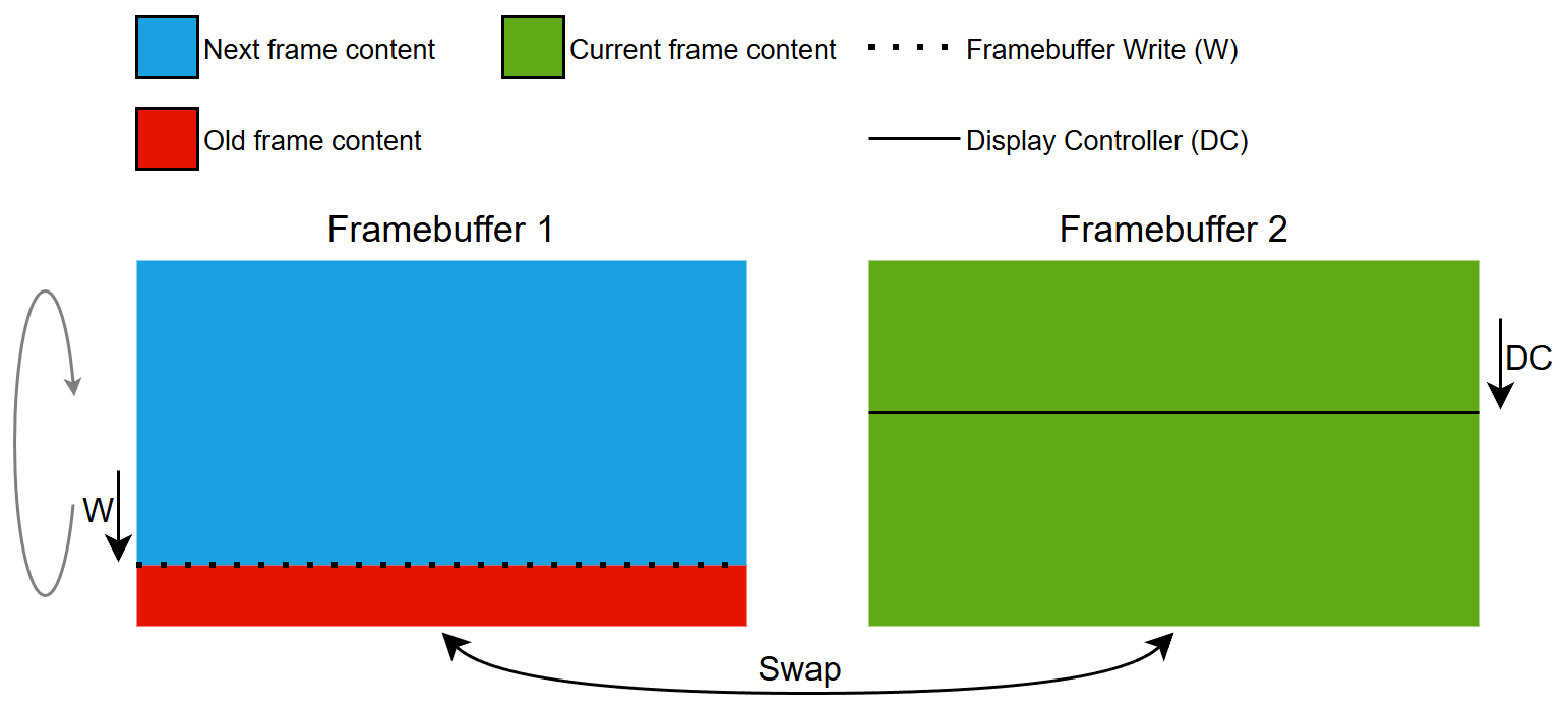
Double Buffering Strategy Concept
Single Buffering Strategy
Having one framebuffer allows rendering of the next frame into the same framebuffer as the Display Controller scans from. Render time of the next frame is restricted by the Display Controller. The Display Controller scans continuously, so if writing to the framebuffer takes too long, the Display Controller will collide (catch up) with the writing area and tearing will occur. This is caused by rendering complex UI components.

Single Buffering Strategy Concept
Partial Buffering Strategy
A single partial framebuffer block is used to emulate a full size framebuffer through a Memory Management Unit (MMU). Therefore this strategy is also known as Emulated Framebuffer Strategy.
The partial block acts as a sliding window moving down through the emulated framebuffer, with the phase and speed of the Display Controller.
Having a partial framebuffer block only allows rendering of a small portion of the next frame, because the block is reused multiple times to render the current frame. The reuse of the partial block results in a large number of small rendering operations, which result in higher CPU load. Render time of the next frame is restricted by the Display Controller and the partial block size. The Display Controller scans continuously, so if writing to the partial framebuffer block takes too long for any given region of the emulated framebuffer, the Display Controller will collide (catch up) with the writing area and tearing will occur. This is caused by rendering complex UI components. Compared to the Single Buffering Strategy the risk of tearing is higher because the working area of the Display Controller and framebuffer rendering is much smaller.
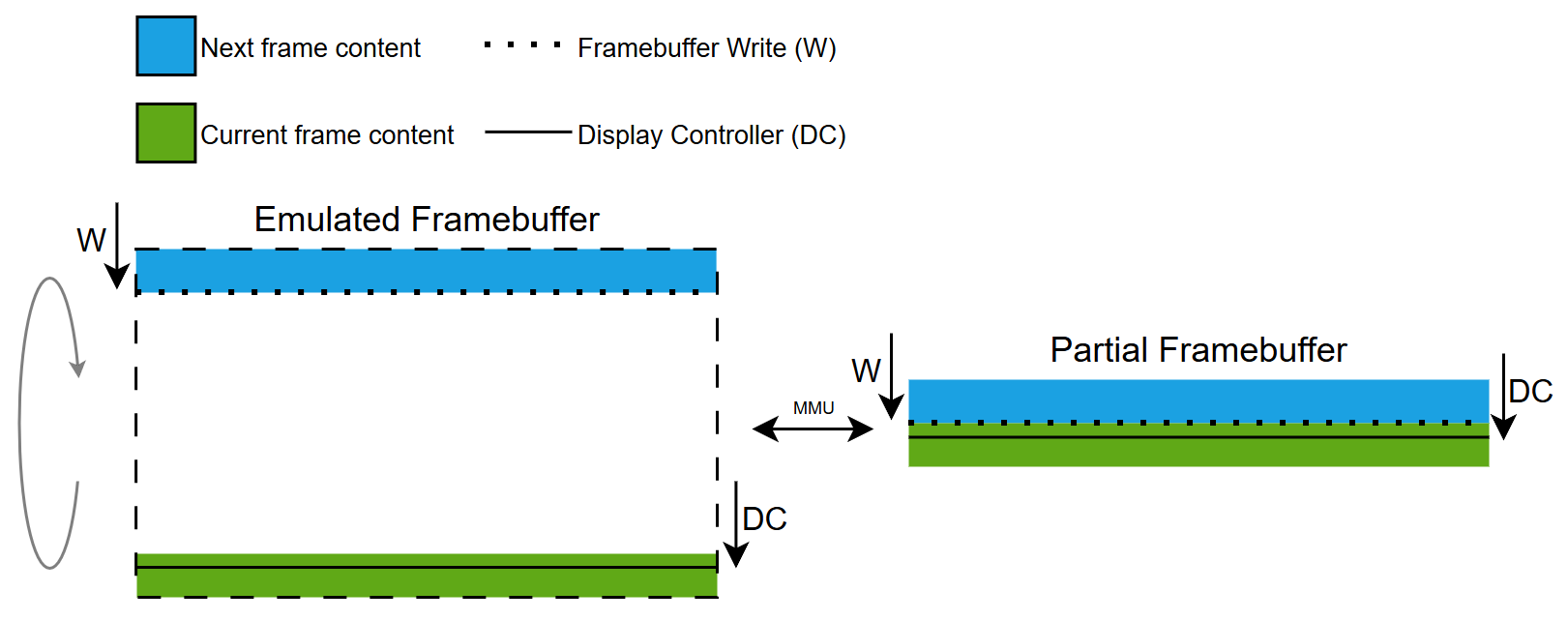
Partial Buffering Strategy Concept
Note
Displays with GRAM
The following demonstrates the working concept of framebuffer strategies on GRAM displays. Common for all strategies are the use of a Display Interface used for transferring pixel data from a framebuffer to the GRAM on the display.
Double Buffering Strategy
Having two framebuffers allows rendering of the next frame into one framebuffer while the pixels are transferred to GRAM from the other. Render time of the next frame is unrestricted by the Display Transfer. Display transfers are only initiated when the next frame is ready, meaning no risk of tearing because the Display Controller just scans what is already in GRAM. The framebuffers are swapped after the display transfer and the rendering is complete.
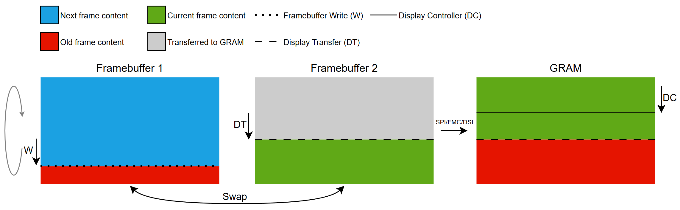
Double Buffering Strategy Concept
Single Buffering Strategy
Having one framebuffer allows rendering of the next frame into the same framebuffer where pixels are transferred to GRAM. Render time of the next frame is restricted by the Display Transfer bandwidth. Display transfers are only initiated when the next frame is ready, meaning no risk of tearing because the Display Controller just scans what is already in GRAM. Rendering of the next frame cannot complete before the corresponding area to update has been transferred to GRAM.

Single Buffering Strategy Concept
Partial Buffering Strategy
One or more partial framebuffer blocks are used to emulate a full size framebuffer.
The partial blocks are reused to render all parts of the current frame that needs to be updated. When a block is rendered it can be transferred to GRAM and used for subsequent rendering.
To minimize the risk of tearing we strive to have the largest margin between GRAM being updated by the Display Transfer and the Display Controller scanline. This is done be having the transferline behind the scanline, which means that we can only render the current frame and not begin rendering the next frame. Render time of the current frame depends on the number of partial blocks defined and the time it takes to transfer each block. This means that we are allowed to render a block that is ahead of the Display Controller scanline if a block is available. If rendering and transferring of all the dirty areas of the current frame takes longer than the Display Controller its scanline can wrap around and catch the transferline, resulting in tearing. This is caused by rendering complex UI components and/or transferring too many pixels.
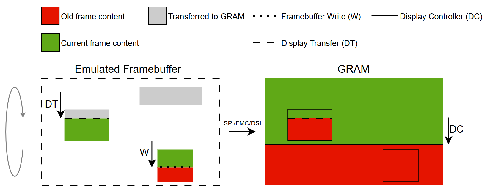
Partial Buffering Strategy Concept
Getting Started with Framebuffer Strategies
In the following section we will show common hardware setups and point to scenarios on how to use framebuffer strategies on various hardware setups.
Further reading
Displays with GRAM
This display type has a dedicated RAM buffer with the same size as the display, i.e. a full size framebuffer.
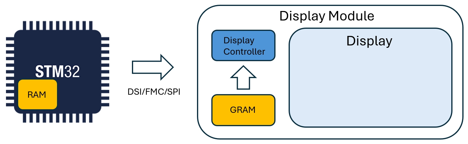
Display with GRAM
The interfaces for this type of display are:
- FMC
- SPI
- DSI (Command Mode)
Scenarios demonstrating the use of these interfaces can be found here:
Displays without GRAM
This display type doesn't have a dedicated RAM buffer.
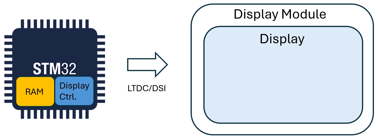
Display without GRAM
The interfaces for this type of display are:
- LTDC
- DSI (Video Mode)
Scenarios demonstrating the use of these interfaces can be found here: