フレームバッファ
フレームバッファは1まとまりのメモリで、ディスプレイに次に表示する画像を格納するためにグラフィック・エンジンによって更新されます。
フレームバッファは、所定のサイズの連続したRAMの領域です。

フレームバッファ・メモリ
フレームバッファには関連付けられた幅と高さがあります。 このため、通常フレームバッファは、XY座標によってインデックス付け可能な2次元でアクセスするメモリであると考えられます。

2Dのフレームバッファ・メモリ
フレームバッファには関連付けられたカラーフォーマットがあります。 フレームバッファの各エントリは、このカラーフォーマットの色になります。 フレームバッファ内のこうしたエントリのことを、ピクセルと呼びます。
フレームバッファ内の(X、Y)位置のピクセルの色を更新するには、フレームバッファ内のピクセルのメモリ・アドレスを計算し、そこに保存されている色を更新します。
uint32_t pixelAddress = x + y * WIDTH;
framebuffer[ pixelAddress ] = newColor;
同様に、フレームバッファ内のピクセルの色を取得し、これを計算で使用できます。 たとえば、フレームバッファ内のピクセルの色を暗くする場合は、次のようになります(darken関数が使用可能だとします)。
uint32_t pixelAddress = x + y * WIDTH;
framebuffer[ pixelAddress ] = darken( framebuffer[ pixelAddress ] );
多くの場合、フレームバッファ・メモリは、上記のようにピクセルごとに読み書きされるのではなく、基盤となるシステムのハードウェア機能(Chrom-ART DMAなど)を利用することで書き込まれます。
色
TouchGFXでは、フレームバッファのピクセルのカラーフォーマットは次のいずれかになります。
- グレースケール: 1、2、または4 bppのグレースケール
- ハイカラーまたはトゥルーカラー: 16、24、または32 bppカラー
使用するbppの値が大きいほど、フレームバッファで表すことのできる色が明瞭になります。さらに、使用するbppの値が大きいほど、フレームバッファに必要なメモリサイズも大きくなります。
ディスプレイ
フレームバッファのコンテンツは最終的には物理ディスプレイに転送され、そこで表示されます。 このため、通常はフレームバッファとディスプレイのピクセルの幅と高さは同じにします。

24 bppフレームバッファのコンテンツとディスプレイ結果
Further reading
フレームバッファの場所
マイクロコントローラ・ベースのグラフィック・システムを非常に簡略化した図を、次に示します。
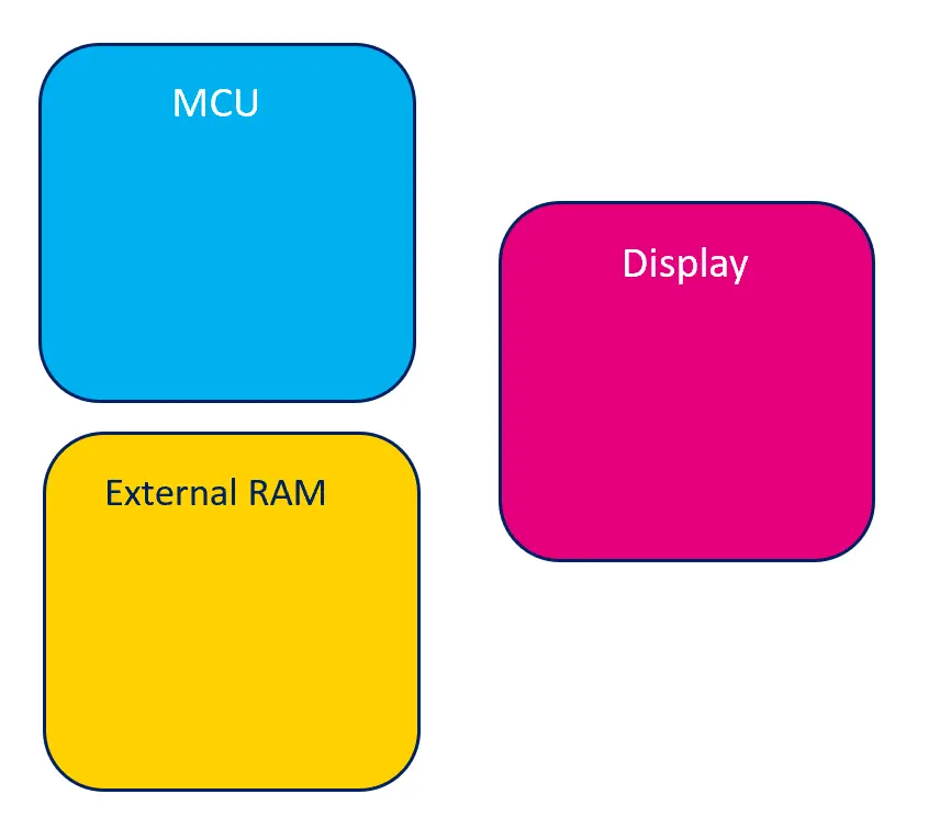
グラフィック・システムを非常に簡略化した図
フレームバッファはマイクロコントローラ内部、または外部RAMに配置できます。
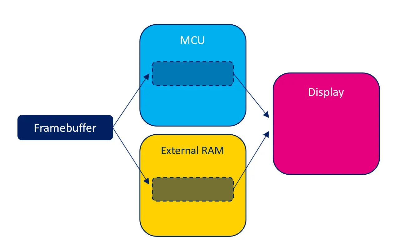
フレームバッファを配置可能な場所
配置可能な場所それぞれに、利点と欠点があります。
内部RAM
フレームバッファをマイクロコントローラ内部のRAMに配置すると、フレームバッファの読み書きアクセスが最大限に高速化されます。 つまり、TouchGFXアプリケーションが可能な限りスムーズに実行されます。 その反面、内部RAMは非常に少量のリソースで、システムの多くの部分によって使用されるため、フレームバッファがこの大部分を占有することは現実的ではないと考えられます。
フレームバッファを内部RAMに配置するとことが可能であれば、追加のRAMが必要なくなるので、システム全体のコストを削減することができます。
外部RAM
システムに外部RAMがある場合、フレームバッファを内部RAMの代わりにこの外部RAMに配置できます。 一般的に、外部RAMに対する読み書きアクセスは内部RAMより低速ですが、外部RAMの容量の方が通常は非常に大きくなります。 このため、場合によってはこれが唯一の解決策になります。
マイクロコントローラには、外部RAMへのアクセスを高速化させる機能(キャッシュなど)が備わっていることがあります。 詳細については、「マイクロコントローラ」のセクションを参照してください。
GRAM搭載ディスプレイ
システム内のディスプレイのタイプによっては、ディスプレイにメモリが内蔵されていることもあります(多くはGRAMと呼ばれます)。 このメモリには、ディスプレイの「物理的な」ピクセルの内容が保持されます。 ディスプレイにこのピクセル・メモリがあると、マイクロコントローラがアイドル状態でもディスプレイが動作を続けることができます。
TouchGFXのフレームバッファをディスプレイ内のRAMに配置することは不可能です。ディスプレイのメモリはメモリ・マップドではなく、ランダムなピクセルの読み書きに適するようにできていないからです。 代わりに、TouchGFXはフレームバッファを内部または外部RAMに配置し、これを適切なタイミングでディスプレイのRAMに転送します。
メモリ使用量
フレームバッファの色の量やピクセル数によって、フレームバッファが必要とするメモリサイズが決まります。
一般的に、フレームバッファで使用されるメモリの量は、幅x高さx色深度(ビット)/ 8 バイトになります。
| 解像度(ピクセル) | 色(bpp) | 計算 | メモリ使用量(バイト) |
|---|---|---|---|
| 800x480 | 16 bpp | 800 x 480 x 16 / 8 | 768,000 B |
| 480x272 | 24 bpp | 480 x 272 x 24 / 8 | 391,680 B |
| 100x100 | 8 bpp | 100 x 100 x 8 / 8 | 10,000 B |
複数のフレームバッファを持つと、それに応じてメモリ使用量も大きくなります。 たとえば、2つのフレームバッファを使用するダブル・バッファリング方式では、メモリ使用量は2倍になります。
1つ未満のフレームバッファを持つ場合、アプリケーションによってメモリの量が明示的に割り当てられ、制御されます。 このためメモリ使用量は完全にカスタマイズ可能になりますが、使用量が少なすぎるとグラフィックス全体のパフォーマンスに悪影響を及ぼすので注意してください。
フレームバッファ戦略
フレームバッファ戦略はグラフィック実装における重要なポイントであり、TouchGFXのレンダリングと既存のハードウェア(マイクロコントローラ、RAM、ディスプレイ)との間の最適なマッチングを可能にします。 新しいハードウェアを選択する場合には、自分の使用例に関連する使用可能なフレームバッファ戦略をよく理解しておくことを推奨します。 適切な選択を行うことはハードウェア・コストの最適化に役立ちます。つまり、フレームバッファのRAMのサイズや適切なディスプレイ・インタフェースの観点から最小限必要なハードウェアを選択するための手助けになります。
フレームバッファ戦略ではフレームバッファに使用されるRAMのサイズを定義し、TouchGFXによるRAMへのレンダリングを制御します。 この戦略は、システムの使用可能なRAMやディスプレイのタイプと一致する必要があります。 TouchGFXは、GRAM搭載のディスプレイ・システムと搭載しないディスプレイ・システムに適用できる3つの異なる戦略を提供しています。 以下の戦略の概要では、ディスプレイ・システムとの関連で各戦略の利点と欠点を示しています。
GRAMを搭載しないディスプレイ
| 戦略 | 利点 | 欠点 | 使用例 |
|---|---|---|---|
| ダブル | ティアリングのリスクがなく、最適なレンダリング時間 | 2つのフレームバッファ用のRAM | 高パフォーマンスのUI |
| シングル | 1つのフレームバッファ用のRAMのみ | ティアリングのリスクがあり、次善のレンダリング時間 | 高から中程度のパフォーマンスのUI |
| パーシャル | 1つ未満のフレームバッファ用のRAMのみ | ティアリングの高いリスクとCPUの高い負荷 | 中程度から低パフォーマンスのUI |
GRAM搭載ディスプレイ
| 戦略 | 利点 | 欠点 | 使用例 |
|---|---|---|---|
| ダブル | ティアリングのリスクがなく、最適なレンダリング時間 | 2つのフレームバッファ用のRAM | 高パフォーマンスのUI |
| シングル | 1つのフレームバッファ用のRAMのみで、ティアリングのリスクなし | 次善のレンダリング時間 | 高から中程度のパフォーマンスのUI |
| パーシャル | 1つ未満のフレームバッファ用のRAMのみ | ティアリングのリスク | 中程度から低パフォーマンスのUI |
ティアリング
ティアリングとは、1つのスクリーン描画に2つのフレームのピクセル・データが表示されているディスプレイ上の視覚的な乱れのことです。たとえば、スクリーンの半分に古いフレーム、もう半分に現在のフレームがあり、明確な横分割(裂け目)が表示されているような状態です。 裂け目(ティアリング)の位置はタイミングに応じて異なり、通常はあちこちにジャンプするので気が散って操作の邪魔になります。
UIのパフォーマンス
一般的なパフォーマンスの記事では、UIのパフォーマンスの各側面が紹介されており、個々のUIコンポーネントとその構造のパフォーマンスへの影響が取り上げられています。 フレームバッファ戦略の文脈では、以下のように考えます。
- 高パフォーマンスとは、複数の複雑なUIコンポーネント/アニメーション(テクスチャ・マッパー、SVG、スクリーン遷移など)を使用するUIのことです。
- 中程度のパフォーマンスとは、少数の複雑なUIコンポーネント/アニメーションを使用するUIのことです。
- 低パフォーマンスとは、複雑なUIコンポーネント/アニメーションを使用しないUIのことです。
Note
用語
以下の用語は、さまざまなフレームバッファ戦略を説明するために使用されています。
- ディスプレイ・コントローラ(DC) - メモリからピクセルを読み出すハードウェア。 ピクセルを含むメモリを読み出し続けます。 スキャンラインと呼ばれることもあります。
- ディスプレイ転送(DT) - フレームバッファ・メモリからGRAMへピクセルを転送するハードウェア。 転送が必要な場合にマイクロコントローラによってのみ開始されます。 転送ラインと呼ばれることもあります。
- フレームバッファへの書き込み(W) - フレームバッファへのピクセルのレンダリング。
GRAMを搭載しないディスプレイ
以下に示すのは、GRAMを搭載しないディスプレイ上のフレームバッファ戦略の実施コンセプトです。 すべての戦略に共通するのは、ディスプレイ・コントローラを使用して、フレームバッファから直接ピクセル・データを絶え間なく読み出し続けることです。
ダブル・バッファリング戦略
2つのフレームバッファを持つことで、次のフレームを1つのフレームバッファ内にレンダリングする間に、ディスプレイ・コントローラがもう一方のフレームバッファをスキャンできます。 次のフレームのレンダリング時間はディスプレイ・コントローラによる制限を受けません。 フレームバッファのスワッピングは次のフレームの準備ができるまでブロックされます。つまり、ディスプレイ・コントローラは準備ができるまで現在のフレームバッファをもう一度スキャンするので、ティアリングのリスクがありません。 フレームバッファのスワッピングは、ディスプレイ・コントローラがフレームバッファ全体のスキャンを完了し、レンダリングが完了した後に行われます。
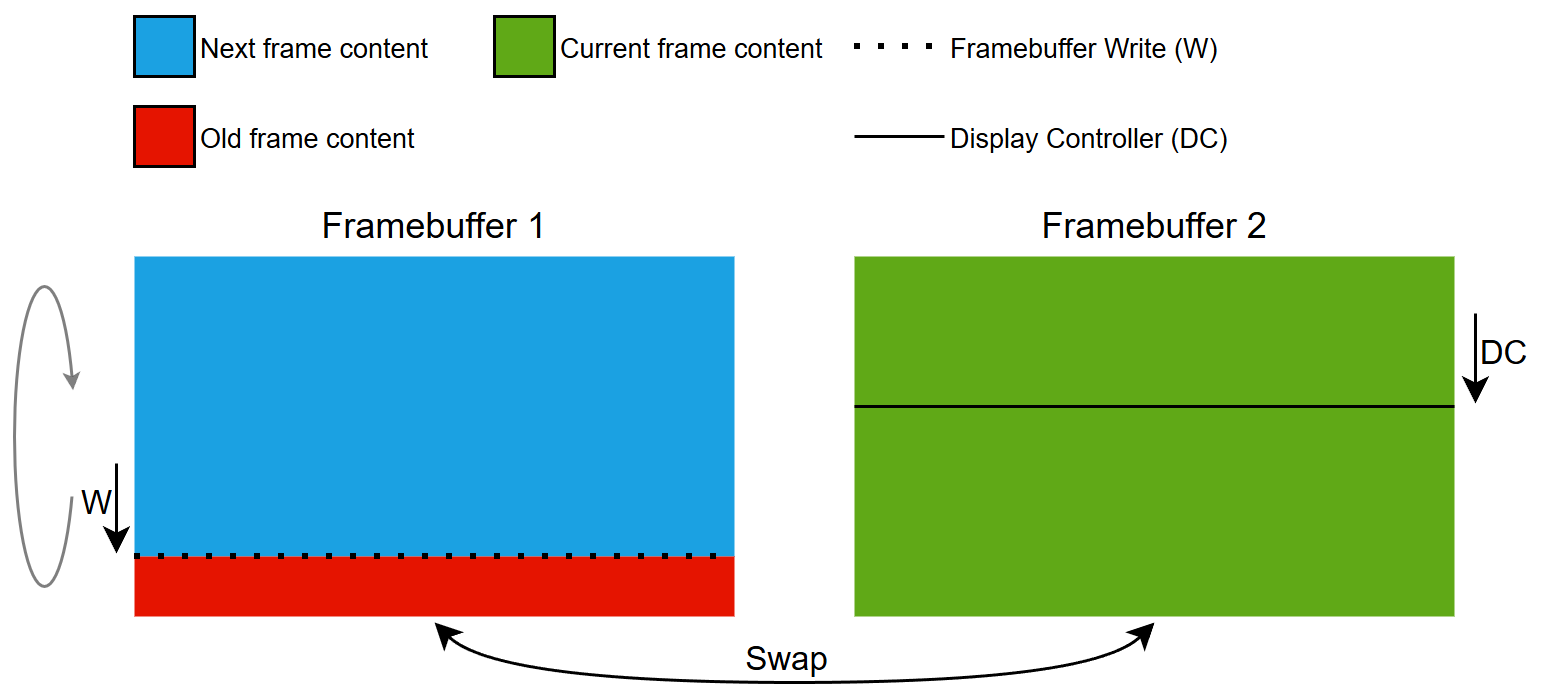
ダブル・バッファリング戦略のコンセプト
シングル・バッファリング戦略
フレームバッファが1つなので、ディスプレイ・コントローラがフレームバッファからスキャンしながら、次のフレームを同じフレームバッファ内にレンダリングします。 次のフレームのレンダリング時間はディスプレイ・コントローラによる制限を受けます。 ディスプレイ・コントローラはスキャンを続けているので、フレームバッファへの書き込みに時間がかかりすぎると、ディスプレイ・コントローラが書き込み領域にぶつかり(追いついて)、ティアリングが発生します。 この状況は複雑なUIコンポーネントのレンダリングが原因で起こります。
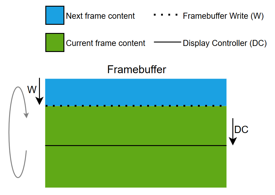
シングル・バッファリング戦略のコンセプト
パーシャル・バッファリング戦略
メモリ管理ユニット(MMU)を介して、1つのパーシャル・フレームバッファ・ブロックを使用してフル・サイズのフレームバッファをエミュレートします。 したがって、この戦略はエミュレートされたフレームバッファ戦略とも呼ばれます。
パーシャル・ブロックがスライディング・ウィンドウの役割を果たし、エミュレートされたフレームバッファを介して、ディスプレイ・コントローラのフェーズと速度で下へ移動します。
パーシャル・フレームバッファ・ブロックでは、次のフレームのごく一部のみをレンダリングします。このブロックを何度も再利用して現在のフレームをレンダリングすることになります。 パーシャル・ブロックの再利用によって多数の小さなレンダリング操作が発生するため、CPU負荷が高まります。 次のフレームのレンダリング時間は、ディスプレイ・コントローラとパーシャル・ブロックのサイズによる制限を受けます。 ディスプレイ・コントローラはスキャンを続けているので、エミュレートされたフレームバッファの特定の領域でパーシャル・フレームバッファ・ブロックへの書き込みに時間がかかりすぎると、ディスプレイ・コントローラが書き込み領域にぶつかり(追いついて)、ティアリングが発生します。 この状況は複雑なUIコンポーネントのレンダリングが原因で起こります。 シングル・バッファリンング戦略と比べて、ティアリングのリスクは高まります。ディスプレイ・コントローラとフレームバッファ・レンダリングのワーク領域がはるかに小さいからです。
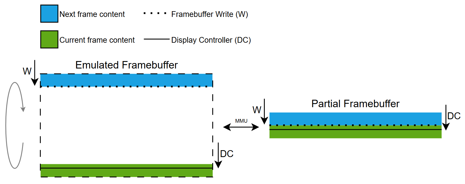
パーシャル・バッファリング戦略のコンセプト
GRAM搭載ディスプレイ
以下に示すのは、GRAM搭載ディスプレイ上のフレームバッファ戦略の実施コンセプトです。 すべての戦略に共通するのは、ディスプレイ・インタフェースを使用して、フレームバッファからディスプレイのGRAMにピクセル・データを転送することです。
ダブル・バッファリング戦略
2つのフレームバッファを持つことで、ピクセルを1つのフレームバッファからGRAMへ転送しながら、もう一方のフレームバッファに次のフレームをレンダリングすることができます。 次のフレームのレンダリング時間はディスプレイ転送による制限を受けません。 ディスプレイへの転送は次のフレームの準備ができた場合にのみ開始されます。つまり、ディスプレイ・コントローラはGRAM内にすでに存在するデータのみをスキャンするので、ティアリングのリスクがありません。 フレームバッファのスワッピングは、ディスプレイへの転送とレンダリングが完了した後に行われます。
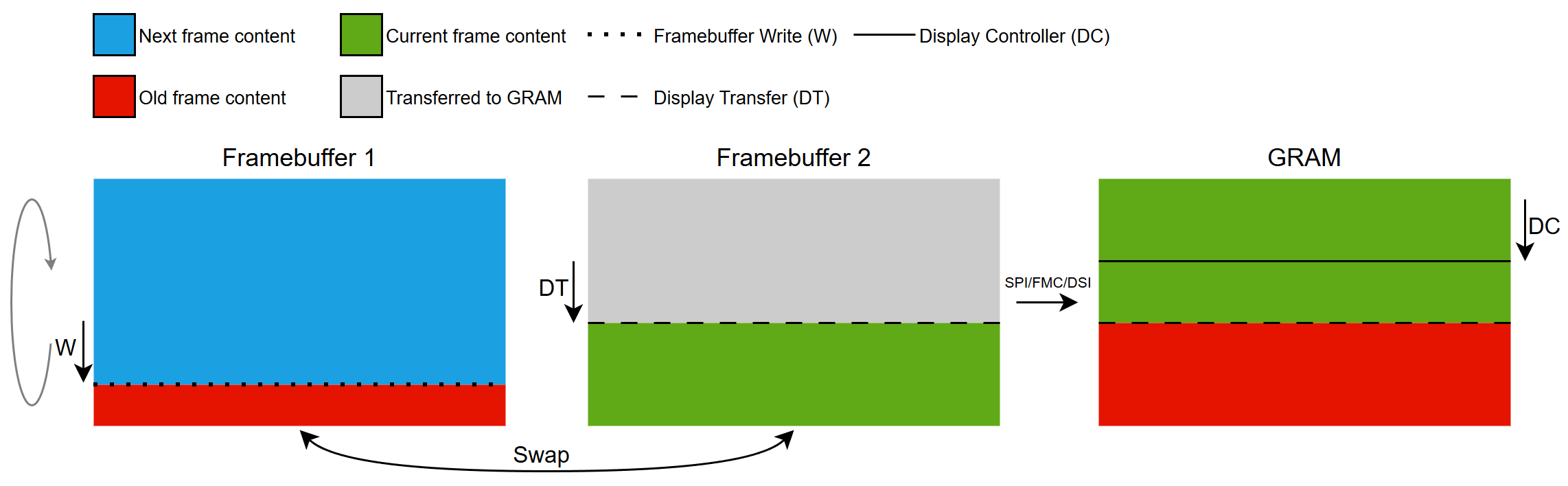
ダブル・バッファリング戦略のコンセプト
シングル・バッファリング戦略
フレームバッファが1つですので、ピクセルがGRAMに転送されている同じフレームバッファ内に、次のフレームをレンダリングすることになります。 次のフレームのレンダリング時間はディスプレイ転送の帯域幅による制限を受けます。 ディスプレイへの転送は次のフレームの準備ができた場合にのみ開始されます。つまり、ディスプレイ・コントローラはGRAM内にすでに存在するデータのみをスキャンするので、ティアリングのリスクがありません。 次のフレームのレンダリングは、更新に該当するエリアがGRAMに転送されるまで完了できません。
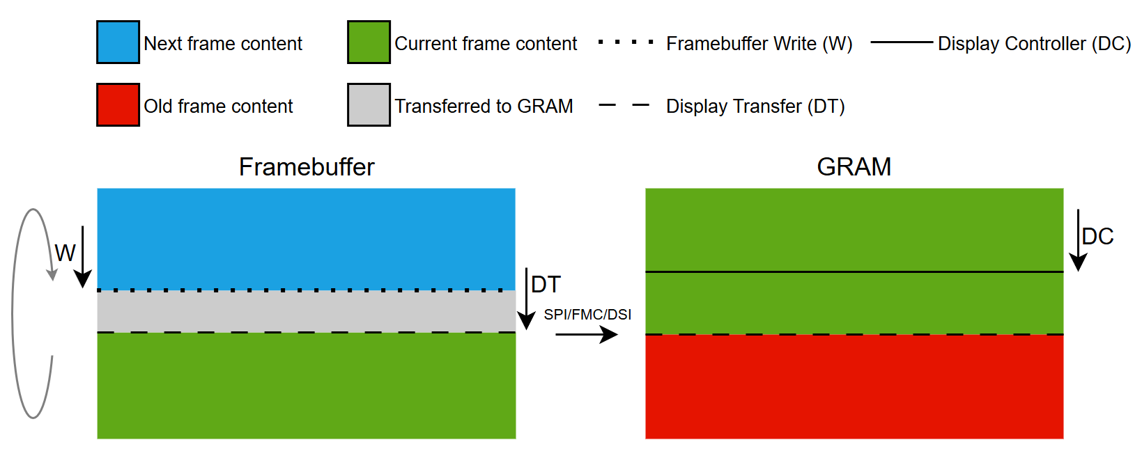
シングル・バッファリング戦略のコンセプト
パーシャル・バッファリング戦略
1つ以上のパーシャル・フレームバッファ・ブロックを使用して、フル・サイズのフレームバッファをエミュレートします。
パーシャル・ブロックを再利用して、現在のフレームで更新の必要なすべての部分をレンダリングします。 1つのブロックがレンダリングされたらそれをGRAMに転送して、後続のレンダリングに使用できます。
ティアリングのリスクを最小限に抑えるため、ディスプレイ転送によって更新されるGRAMとディスプレイ・コントローラのスキャンラインの間に最大限のマージンをとるように努めています。 このため、スキャンラインの背後に転送ラインを設けているので、現在のフレームのみがレンダリング可能で、次のフレームのレンダリングは開始できません。 現在のフレームのレンダリング時間は、定義されたパーシャル・ブロックの数と各ブロックの転送にかかる時間によって異なります。 つまり、1つのブロックが使用可能な場合、ディスプレイ・コントローラのスキャンラインの前にあるブロックのレンダリングが可能となります。 現在のフレームのすべてのダーティ・エリアのレンダリングと転送に、ディスプレイ・コントローラより長い時間がかかっている場合、スキャンラインのラップ・アラウンドが発生し、転送ラインに追いついてしまい、ティアリングが発生します。 この状況は複雑なUIコンポーネントのレンダリングや、過剰な数のピクセル転送が原因で起こります。
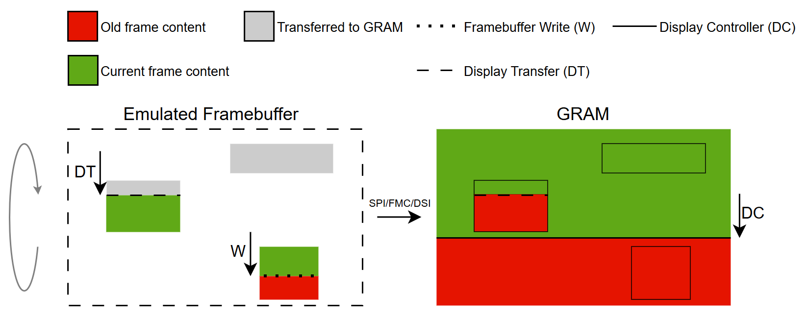
パーシャル・バッファリング戦略のコンセプト
フレームバッファ戦略入門
次のセクションでは、一般的なハードウェアのセットアップを示し、さまざまなハードウェア・セットアップでフレームバッファ戦略を使用するシナリオを提示します。
Further reading
GRAM搭載ディスプレイ
このディスプレイ・タイプには、ディスプレイと同じサイズの専用のRAMバッファ(フルサイズのフレームバッファ)が搭載されています。
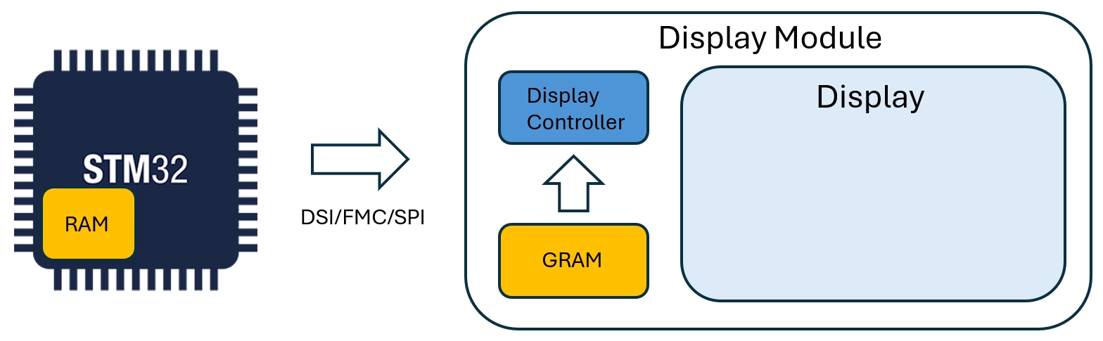
GRAM搭載ディスプレイ
このタイプのディスプレイのインタフェースは以下のとおりです。
- FMC
- SPI
- DSI(コマンドモード)
これらのインタフェースの使用をデモンストレーションするシナリオには、以下のリンクからアクセスできます。
GRAMを搭載しないディスプレイ
このディスプレイ・タイプは専用のRAMバッファを搭載していません。
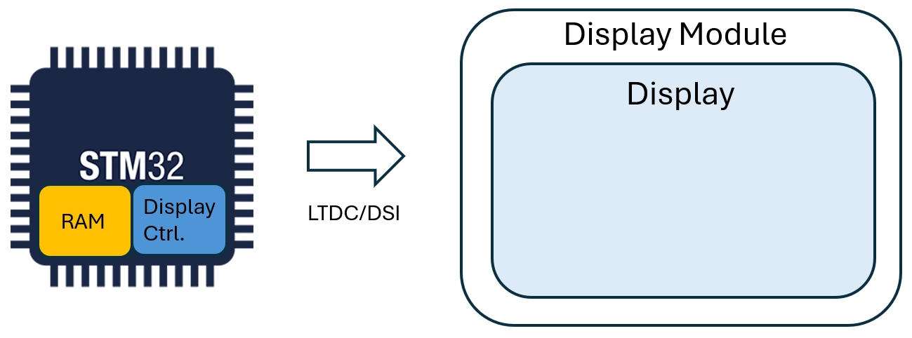
GRAMを搭載しないディスプレイ
このタイプのディスプレイのインタフェースは以下のとおりです。
- LTDC
- DSI(ビデオ・モード)
これらのインタフェースの使用をデモンストレーションするシナリオには、以下のリンクからアクセスできます。