Performance Measurement
TouchGFX Core exposes several signals that can be used to measure performance. Users can instrument their applications to trigger individual GPIOs when these signals are triggered internally, allowing visualization of "render time" and other useful signals. This article covers how to configure GPIOs in STM32CubeMX and what each exposed signal does.
Further reading
Signals exposed by TouchGFX Core
The following signals are defined within the TouchGFX Core headerfile GPIO.hpp:
| Signal | Description |
|---|---|
| VSYNC_FREQ | TouchGFX applications are driven by internal or external events like interrupts from an LTDC, external peripherals or hardware timers. When the TouchGFX Engine has finished rendering it waits for the VSYNC signal. It indicates when the display has finished updating so TouchGFX can start rendering the next frame. |
| RENDER_TIME | This is the time from when a frame is transferred to TouchGFX to the end of the rendering phase. |
| FRAME_RATE | This is the frame rate of the user application. The signal toggles when a frame is updated. If render time exceeds the max render time defined by the display, the frame rate will drop. |
| MCU_ACTIVE | this signal is high whenever TouchGFX used the MCU. The MCU is active when the framebuffers are transferred and when TouchGFX is doing work i.e. not in the idle task. |
STM32CubeMX GPIO configuration
STM32CubeMX can be used for easy configuration of GPIO output pins. By giving each Pin a User Label, the code generated by by TouchGFX Generator in TouchGFXGPIO.cpp know which pin to toggle when a signal is received internally from TouchGFX Core.
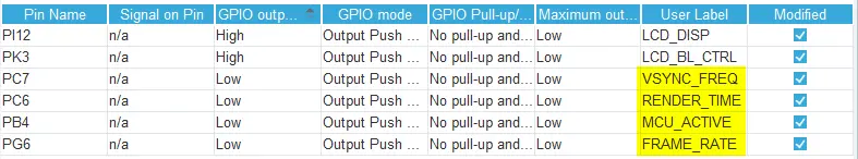
In the Pinout view configure four unused GPIO's as outputs. In STM32CubeMX GPIO IP give the User Label for each pin a label that match the specific name defined by TouchGFX Core that should be triggered through a GPIO (i.e. VSYNC_FREQ, RENDER_TIME, FRAME_RATE or MCU_ACTIVE. ).
TouchGFXGPIO Class
TouchGFX Generator generates the functions for the GPIO class in the file TouchGFXGPIO.cpp.
TouchGFX Core calls functions on the TouchGFXGPIO class which then toggles pins based on the users configuration in STM32CubeMX. GPIO::set is shown in the snippet below:
TouchGFXGPIO.cpp
void GPIO::set(GPIO_ID id)
{
    switch (id)
    {
    case GPIO::VSYNC_FREQ:
#if defined(VSYNC_FREQ_GPIO_Port) && defined(VSYNC_FREQ_Pin)
        HAL_GPIO_WritePin(VSYNC_FREQ_GPIO_Port, VSYNC_FREQ_Pin, GPIO_PIN_SET);
#endif
        break;
    case GPIO::RENDER_TIME:
#if defined(RENDER_TIME_GPIO_Port) && defined(RENDER_TIME_Pin)
        HAL_GPIO_WritePin(RENDER_TIME_GPIO_Port, RENDER_TIME_Pin, GPIO_PIN_SET);
#endif
        break;
    case GPIO::FRAME_RATE:
#if defined(FRAME_RATE_GPIO_Port) && defined(FRAME_RATE_Pin)
        HAL_GPIO_WritePin(FRAME_RATE_GPIO_Port, FRAME_RATE_Pin, GPIO_PIN_SET);
#endif
        break;
    case GPIO::MCU_ACTIVE:
#if defined(MCU_ACTIVE_GPIO_Port) && defined(MCU_ACTIVE_Pin)
        HAL_GPIO_WritePin(MCU_ACTIVE_GPIO_Port, MCU_ACTIVE_Pin, GPIO_PIN_SET);
#endif
        break;
    }
}
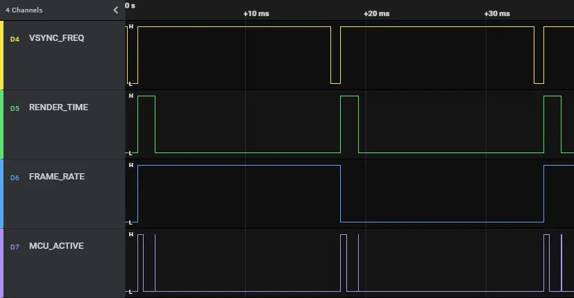
If a pin has the user label VSYNC_FREQ STM32CubeMX will automatically generate matching symbols for Port, Pin, e.g. VSYNC_FREQ_GPIO_Port, VSYNC_FREQ_Pin. To measure the configured signals use an oscilloscope or logic analyser. The image below shows a logic analyser displaying each of the four signals. The application is running on an STM32F746G-DISCO with the Animated Image UI Example. The VSYNC signal for this application is generated by the LTDC every 16ms.