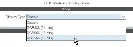
LTDC Display Interface
This scenario describes how to configure the STM32 LTDC display controller and TouchGFX Generator when using a LCD-TFT parallel display interface.
The TouchGFX Generator can generate a full TouchGFX AL that configures the LTDC to transfer pixels from the framebuffer memory to the display and synchronize the display with the TouchGFX Engine.
Configuration
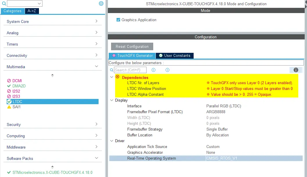
Enable the LTDC from the Multimedia group in the STM32CubeMX category list.
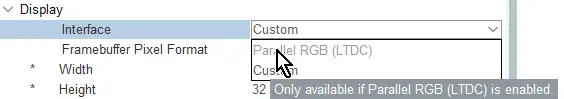
Once LTDC is enabled, the Parallel RGB (LTDC) option becomes available through the Display section of the TouchGFX Generator.
After LTDC is enabled through STM32CubeMX, the following parameters must be configured:
- Configure LTDC (GPIO and timings) to match connected display specifications
- Configure LTDC to match desired TouchGFX application specifications.
The TouchGFX Generator can read various configurations from STM32CubeMX and provide a list of warnings, recommendations or errors in the Dependencies section. The image below shows the list of dependencies present when initially enabling LTDC in STM32CubeMX:
Note
Parameter and Layer Configuration
The following parameters must be configured in the LTDC block:
| Dependency | Description |
|---|---|
| Number of layers | TouchGFX is only capable of utilizing a single layer. |
| Window position | By default, the Horizontal and Vertical window positions of the LTDC layer are 0. The window Horizontal and Vertical stop must be set equal to the displays dimensions. |
| Alpha Constant is 0 | By default, the alpha constant of LTDC layers is 0. This should be > 0 and preferably 255 unless there is an intent to have a global alpha at all times in an application. |
The following image shows the LTDC configuration that satisfies the conditions of the warnings, causing the Dependencies group to disappear from the TouchGFX Generator interface.

Note
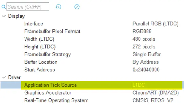
TouchGFX Driver / VSYNC Signal
Once Parallel RGB (LTDC) is selected as Display Interface, developers gain access to the LTDC Application Tick Driver, which use the LTDC interrupt to drive the TouchGFX Engine main loop. This is the recommended way to drive the TouchGFX Engine main loop when using LTDC.
Note
The following code is a generated LTDC interrupt handler (for single or double framebuffer strategy) that automatically signals and unblocks the TouchGFX Engine main loop when the display is ready.
TouchGFXGeneratedHAL.cpp
extern "C"
{
    void HAL_LTDC_LineEventCallback(LTDC_HandleTypeDef* hltdc)
    {
        if (!HAL::getInstance())
        {
            return;
        }

        if (LTDC->LIPCR == lcd_int_active_line)
        {
            //entering active area
            HAL_LTDC_ProgramLineEvent(hltdc, lcd_int_porch_line);
            HAL::getInstance()->vSync();
            OSWrappers::signalVSync();

            // Swap frame buffers immediately instead of waiting for the task to be scheduled in.
            // Note: task will also swap when it wakes up, but that operation is guarded and will not have
            // any effect if already swapped.
            HAL::getInstance()->swapFrameBuffers();
            GPIO::set(GPIO::VSYNC_FREQ);
        }
        else
        {
            //exiting active area
            HAL_LTDC_ProgramLineEvent(hltdc, lcd_int_active_line);

            // Signal to the framework that display update has finished.
            HAL::getInstance()->frontPorchEntered();
            GPIO::clear(GPIO::VSYNC_FREQ);
        }
    }
}
LTDC Frame Buffer address configuration
The generated TouchGFX HAL will automatically configure the LTDC Layer Color Frame Buffer Start Address at runtime, so you should not set a value in LTDC configuration.
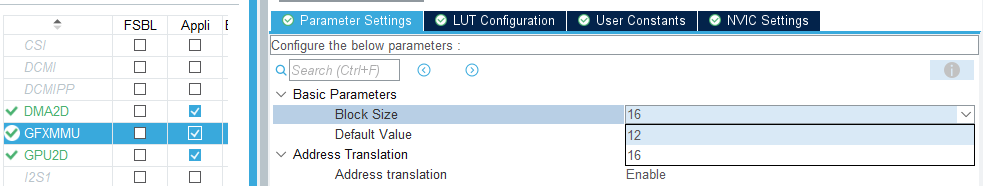
GFXMMU configuration
When using Partial Buffer - LTDC driven display framebuffer strategy, the GFXMMU must be enabled and configured. The GFXMMU is used to map the framebuffer addresses that are read by the LTDC to the addresses of the partial framebuffer block in physical memory.
First, enable the GFXMMU in STM32CubeMX under the Multimedia section, and enable Address Translation. For 16- and 32-bit framebuffer pixel formats a Block Size of 16 bytes is recommended. For 24-bit framebuffer pixel formats a Block Size of 12 bytes is required.
Note
Caution
The TouchGFX Generator will automatically generate an address look-up table (LUT) that maps the addresses based on the GFXMMU configurations and LTDC layer settings.
After enabling the GFXMMU, the number of partial blocks used (or the number of times the partial framebuffer block fits into the display) can be configured in the TouchGFX Generator.
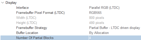
This parameter will directly impact the amount of RAM used for the framebuffer block. The number of blocks must be a power-of-2, e.g., 2, 4, and 8, which results in a framebuffer block of size 1/2, 1/4, and 1/8 of total display size respectively.
Framebuffer allocation
When using Partial Buffer - LTDC driven display framebuffer strategy, the semantics of the framebuffer allocation strategy are different than usual.
If choosing by allocation, the TouchGFX Engine will draw directly into the physical partial framebuffer block, while the LTDC reads through the GFXMMU address LUT.
If choosing by address, only the address of one of the GFXMMU virtual buffers can be specified and the TouchGFX Engine will draw through the virtual buffer of the GFXMMU when rendering, instead of directly into the physical framebuffer block.
Buffer Location - By allocation
The recommended framebuffer allocation strategy is by allocation. This allows the TouchGFX Engine to draw directly into the physical partial framebuffer block, while the LTDC reads through the GFXMMU address LUT.
Buffer Location - By address
This option is only recommended on some specific platforms with limitations using RGB888 framebuffer format and GPU2D (NeoChrom) to accelerate rendering.
Some MCU's using GPU2D (NeoChrom) to accelerate rendering do not support writing to a 24-bit RGB888 framebuffer. In this case, the GFXMMU is used to pack data that is read/written from a 32-bit ARGB8888 format to the RGB888 format of the physical framebuffer block.
Further reading
To enable this, the LTDC Pixel format must be setup to use the ARGB8888 framebuffer format and use one of the virtial buffers of the GFXMMU GFXMMU_VIRTUAL_BUFFERX_BASE as the framebuffer address. It is important to use the same GFXMMU buffer address that
configured in the GFXMMU.
Configure the GFXMMU to use a Block Size of 12 bytes, and enable Packing for the buffer as shown below:
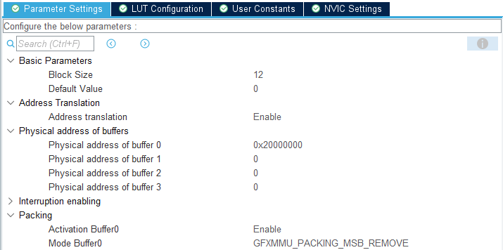
These options will be reflected in the TouchGFX Generator UI:
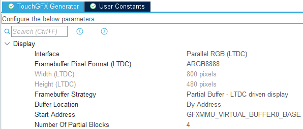
The physical 24-bit framebuffer memory region must be defined in the linker script with the correct size (i.e., 3 bytes per pixel) and the start address of this region must be used to configure the physical buffer address of the GFXMMU.
Note
Supported Framebuffer Strategies
- Single
- Double
- Partial - LTDC driven display
Further reading
Single
Using a LTDC driven display with the single framebuffer strategy, will generate the following code in the HAL to allow the TouchGFX Engine to follow the refresh cycle of the display to optimize the rendering process:
TouchGFXGeneratedHAL.cpp
uint16_t TouchGFXGeneratedHAL::getTFTCurrentLine()
{
    // The CPSR register (bits 15:0) specify current line of TFT controller.
    uint16_t curr = (uint16_t)(LTDC->CPSR & LTDC_CPSR_CYPOS_Msk);
    uint16_t backPorchY = (uint16_t)(LTDC->BPCR & LTDC_BPCR_AVBP_Msk) + 1;

    // The semantics of the getTFTCurrentLine() function is to return a value
    // in the range of 0-totalheight. If we are still in back porch area, return 0.
    return (curr < backPorchY) ? 0 : (curr - backPorchY);
}
In the LTDC interrupt handler, the LTDC framebuffer address will not be swapped and the TouchGFX Engine is allowed to finish rendering the current frame when the display refresh cycle has exited the active area, which is when the display have read the last line of the framebuffer.
Reference implementation
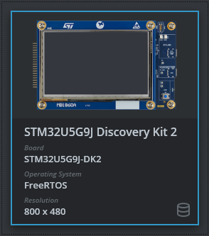
The TouchGFX Board Setup STM32U5G9J Discovery Kit 2 includes a reference implementation of double framebuffer strategy. Change the framebuffer strategy to single in the TouchGFX Generator and generate code to see an example of using single framebuffer strategy:
Double
When using an LTDC driven display with the double framebuffer strategy, the LTDC framebuffer address will be swapped to the other framebuffer in the LTDC interrupt handler. This allows the TouchGFX Engine to render the next frame immediately after swapping the LTDC framebuffer address, while the LTDC is reading the current frame from the other framebuffer.
Reference implementation
The TouchGFX Board Setup STM32U5G9J Discovery Kit 2 includes a reference implementation:
Partial - LTDC driven display
Using a LTDC driven display with the Partial framebuffer strategy, is similar to using single framebuffer strategy, but the TouchGFX Engine will only render into the partial framebuffer block. Because the same framebuffer block is reused to render all parts of the display, it is important to efficiently manage the rendering process to avoid tearing and missing hard deadlines. To enable this, the TouchGFX Generator will generate the following code in the HAL to allow the TouchGFX Engine to configure LTDC line interrupts to signal the TouchGFX Engine when to render the next part of the display:
TouchGFXGeneratedHAL.cpp
void TouchGFXGeneratedHAL::waitForLTDCLines(uint16_t numberOfLines)
{
    // The CPSR register (bits 15:0) specify current line of TFT controller.
    uint16_t curr = LTDC->CPSR & LTDC_CPSR_CYPOS_Msk;

    // The AWCR register (10:0) specify the accumulated active height.
    uint16_t max = (LTDC->AWCR & LTDC_AWCR_AAH_Msk) - 1;

    // Calculate the line at which to configure the interrupt.
    curr += numberOfLines;
    if (curr > max)
    {
        curr -= max;
    }

    // Configure line interrupt
    HAL_LTDC_ProgramLineEvent(&hltdc, curr);

    // Wait for VSync signal, which fires on the line interrupt that we just configured.
    OSWrappers::waitForVSync();
}
The function TouchGFXGeneratedHAL::waitForLTDCLines(uint16_t) is called from the TouchGFX Engine drawing loop. The specific number of line being requested depends on a set of parameters.
Depending on the Number Of Partial Blocks that are configured in the TouchGFX Generator, a set of appropriate default values will be assigned to these parameters.
Because the framebuffer block is reused to render all parts of the display, the VSYNC signal which normally signals the LTDC scanline has left the active area, is used to signal the TouchGFX Engine to start rendering the next part of the display:
TouchGFXGeneratedHAL.cpp
extern "C"
{
    void HAL_LTDC_LineEventCallback(LTDC_HandleTypeDef* hltdc)
    {
        OSWrappers::signalVSync();
    }
}
Reference implementation
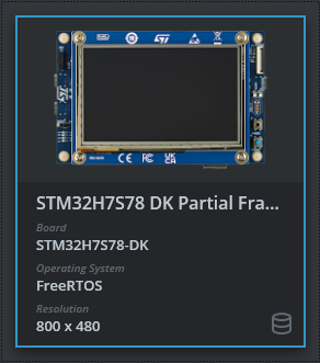
The TouchGFX Board Setup STM32H7S78 DK Emulated Framebuffer includes a reference implementation: