TouchGFX on Low Cost Hardware
This section discusses how to use TouchGFX on low cost hardware with limited amount of RAM and flash, no acceleration and slow connection to external flash and display.
We will try to give some advice on writing the best applications of the given hardware.
Throughout this section we will use the TouchGFX board setup for the STM32G071 nucleo board with the X-Nucleo-GFX01M1 expansion board as example hardware.
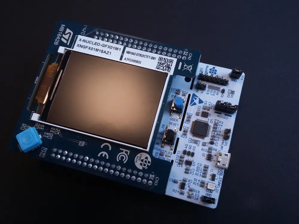
Nucleo-G071RB with X-Nucleo-GFX01M1 expansion board
Hardware Overview
The hardware setup in this kit consist of the STM32G071 MCU, a SPI NOR flash, a SPI display, and joystick button.
| Component | |
|---|---|
| MCU | STM32G071RB |
| MCU RAM | 32 Kb |
| MCU Flash | 128 Kb |
| Display | Displaytech DT022CTFT |
| Display resolution | 240 x 320 |
| Display controller | ILI9341V |
| Display connection | SPI |
| Display connection speed | 32 MHz |
| NOR Flash | Macronix MX25L6433F |
| NOR Flash size | 64 Mbit |
| NOR Flash connection speed | 32 MHz |
The display is connected to the SPI1 peripheral and the flash is connected to the SPI2 peripheral. This allows the MCU to read data from the flash while transmitting data to the display.

Nucleo-G071RB with X-Nucleo-GFX01M1 architecture
GPIO Allocation
| Signal | GPIO Pin |
|---|---|
| Display CS | PB5 |
| Display DCX | PB3 |
| Display SCK | PA5 |
| Display MOSI | PA7 |
| Display TE | PA0 |
| Flash CS | PB9 |
| Flash SCK | PB13 |
| Flash MOSI | PC3 |
| Flash MISO | PC2 |
The table above lists the GPIO allocation for the signals to the flash and display. These signal can be monitored with a oscilloscope or logic analyzer. This is very usefull during debugging of e.g. performance problems.
Starting a Project
It is easy to start a project for the STM32G071RB Nucleo evaluation kit in the TouchGFX Designer. Click on the "Create New" button and search for STM32G071 Nucleo. This board setup is developed specifically for the Nucleo-G071RB kit with the X-Nucleo-GFX01M1 display shield.
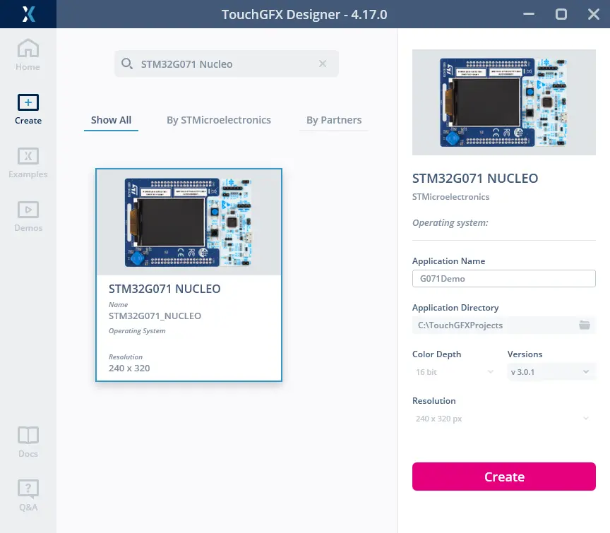
New project for Nucleo-G071RB
The TouchGFX board setup supports the NOR flash, the display, and the buttons. The display can be used both in portrait and horisontal mode.
The display orientation can be change in the TouchGFX Designer in the Config -> Display section:
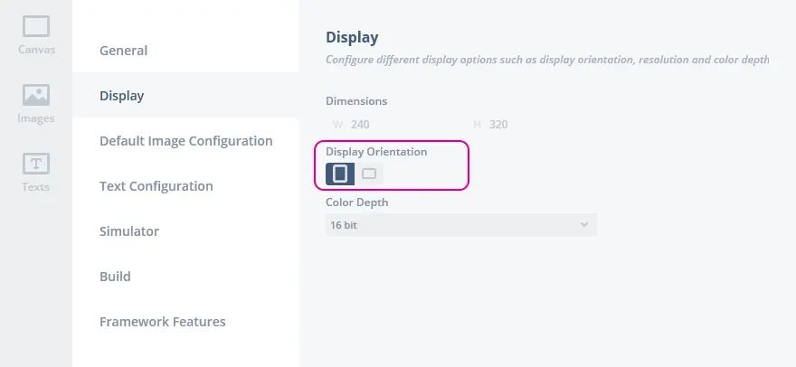
Selecting portrait or horizontal display orientation
The display on the X-Nucleo-GFX01M1 shield is natively portrait orientated (higher than wide), but it can easily be used with horizontal orientation.
Display Updates
As mentioned above the display resolution is 240 x 320 pixels. A total of 76.800 pixels or 153.600 bytes. The SPI connection between the MCU and the display is running at 32 MHz. This allows us to transfer 4 MBytes/s or 2M pixels/s.
The refresh rate of the display is 76.1 Hz which gives us a frame time of 13.14 ms.
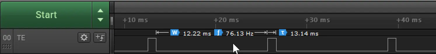
Tearing effect signal from the display
This means that we have at most 13 ms to send data for the next
frame. In that time we can send 2.000.000 pixels/s / 76 fps = 26.280
pixels / frame or 34% of a full screen.
In practice we cannot sustain that transfer speed on the SPI bus
because of the protocol overhead so we cannot expect to send more than
approximately 30% of a full frame.
If the application updates more than that amount of pixels the hardware cannot complete the transmission within the frame time. The result is that the display will start showing the updated frame before it is completely updated. The user will then in some cases see a mix of the old frame and the new frame.
For some animations this is not noticeable to the user, for others the result will be unacceptable.
We therefore recommend to keep the level of updates below the 30% limit. E.g. by incrementally updating the frame step-by-step.
Because of this, it is generally better to expand an item on the screen, than moving the item.
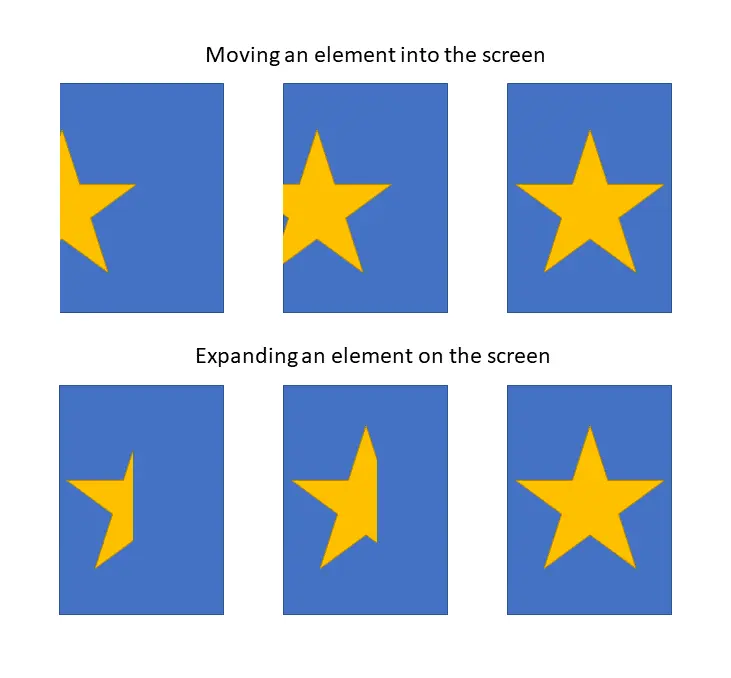
Tearing effect signal from the display
When the star is moved to the right, all the pixels covered by the star must be updated. When the star is expanded only the new pixels must be updated. The pixels updated in previous frame remain unchanged.
Drawing Speed
The transmission to the display is running at maximum 32 MHz.
The serial flash can run at the same speed as the display transmission. This means that the serial flash is fast enough to feed bits to the display at maximum speed.
This is only achieved if the pixel format of an image in the flash is
RGB565. In this case is two bytes read from the flash equal to 1
pixel, which is also two bytes on the display.
If the pixel format in the flash is ARGB8888, we need to read double
the amount of data from the flash to produce a pixel on the display,
and the serial flash will not be able to keep up with the display.
When this happens we are not sending data to the display continously and it will not be possible to update all 30% of the display in a frame. One possibility is to move the image to internal flash, another of course to change the pixel format.
Other widgets are not bound by the speed of the flash. E.g. the Box Widget, which draws a colored rectangle. This widget is of course very fast and much faster than the display transmission. Other widgets like Line and Circle uses much more CPU resources. These Widget are not able to produce pixels in the speed they can be transmitted to the display. Using these Widgets an application cannot expect to be able to update 30% of the display in every frame.
Find about pixel rendering complexity here
TouchGFX Limitations with Serial Flash
TouchGFX on STM32G0 with serial flash has a few limitations that the application programmer must be aware of.
Texture Mapper
The texture mapper widgets (Texture Mapper, Animation Texture Mapper, Scalable Image) can not draw an image that is stored in the external SPI flash. The reason is that it is not possible to get an acceptable performance of e.g. image rotation with an image stored in a serial flash.
To use an image with a texture mapper you must store the image in internal flash or RAM. An image is easily stored in internal flash by modifying the image configuration in TouchGFX Designer.
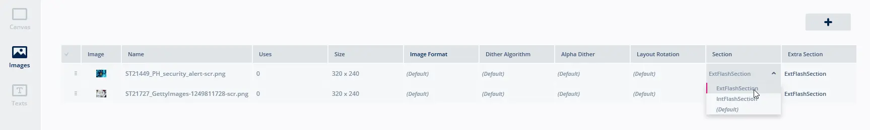
Go to the Images tab and select the image. In the right side of the window, change the "Section" attribute to "IntFlashSection".
Placing an image in internal flash
The texture mapper code is too large to include in all projects. It is therefore disabled pr. default for STM32G0 projects. This means that you must enable the texture mapper before you can use it in your STM32G0 projects.
Go to the "Config" tab, select "Framework Features", and click the relevant texture mapper or a group of texture mappers.
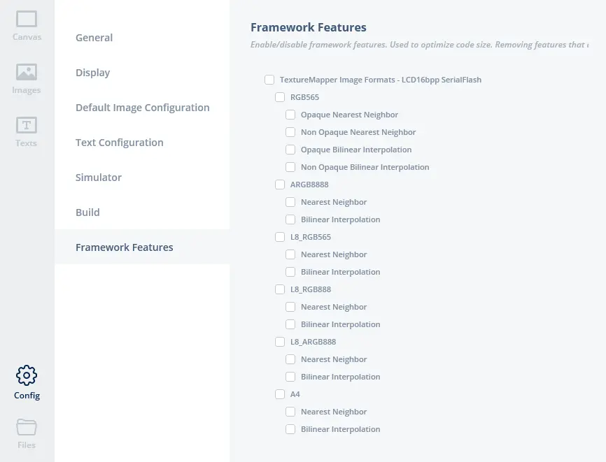
Enabling a texture mapper for a specific image format
It is also possible to temporarily move an image to RAM using the Bitmap Cache
Bitmap Painter
Line, Circle, and Dynamic Graph widgets can be colored with an image. This is not possible with images located in the SPI flash. Images used with these widgets must be placed in internal flash or RAM.
L8 Palette
Images in L8 format can be used on hardware with a serial flash. The limitation is that the palette data must be in the internal flash (also for performance reasons).
The palette can be moved to internal flash by changing the "Extra Section" to "IntFlashSection" in the TouchGFX Designer.
Drivers
The TouchGFX board setup is created using the TouchGFX Generator. Read
more about the Generator
here. The
TouchGFX Generator generates a HAL layer that links the TouchGFX
framework with a set of low-level drivers (already implemented in this
TouchGFX board setup). The low-level drivers for this application
template are located in the Core/Src folder in your project.
The drivers are in 3 files:
| Driver | File |
|---|---|
| Display | Core/Src/MB1642BDisplayDriver.c |
| Flash | Core/Src/MB1642BDataReader.c |
| Buttons | Core/Src/MB1642BButtonController.cpp |
Display
The display uses a fairly standard SPI protocol. A number of registers is the diplay can be written to configure the display. The chip select is asserted when data is transmitted to the display. An extra GPIO, DCX, is used to differentiate command bytes from data bytes.
The driver uses a DMA channel to send display pixel data. This allows the transmission to run while the MCU is calculating pixels. An DMA complete interrupt is used to free the memory transmitted for reuse in a future drawing and to restart the transmission if new data is already available.
Configuration data is not send with DMA, because the CS and CDX pins must be toggle between and in the small configuration packages.
The driver uses the SPI in 8 bit mode when sending configuration data, but changes to 16-bit mode when transmitting the pixel data. The reason for this is that the MCU memory is read in little endian mode. A pixel in RGB565 format is stored in RAM with the low byte (G and B) first and the high byte (R and G) second. This order is preserved when the 8-bit SPI is reading the memory for transmission. When the SPI is in 16-bit mode, the data is read as 16-bit RGB565 from memory and transmitted in correct order for the display.
A driver not using 16-bit DMA must swap the bytes in a pixel before transmitting.
Initialisation
The display initialisation is found in the function MB1642BDisplayDriver_DisplayInit(void)
The driver sends 6 commands to the display which follows the recommended power on sequence:
- Exit Sleep Mode (11h)
- Enter Normal Mode (13h)
- Set Memory Access Control (36h) with MX and BGR bits set
- Set Pixel Format (3Ah) with format 16 bits
- Tearing Effect Line On (35h)
- Set Tear Scanline (44h) with line = 0
The driver sleeps for 100 ms between these command.
Tearing Effect
The Tearing Effect (TE) signal from the display is very important. It allows the application to synchronize correctly with the display. This helps the application to avoid tearing on the display. The display asserts the signal whenever it starts an update cycle. The MCU uses this signal to also sending data to the display.
The TE signal is connected to the external interrupt input of the MCU. CubeMx generates and configures an interrupt on this pin.
The callback in the driver signal TouchGFX to start drawing:
MB1642BDisplayDriver.c
void HAL_GPIO_EXTI_Rising_Callback(uint16_t GPIO_Pin)
{
  ...
  touchgfxSignalVSync();
}
External flash
The SPI NOR flash on the display shield is a standard SPI flash. The driver is simpler than the display driver. No special initialisation is required to read data from the flash.
The driver can read data using polled SPI (busy waiting for each byte) or DMA. The time to start a DMA reception is similar to the time it takes to read 20 bytes in polled mode, so it is often slower for short reads. On the other hand, the DMA continues to run during interrupt and can run in the background when the MCU is busy rendering pixels. For this reason both methods are used.
The flash driver is using another DMA channel than the display driver, so both reception of data and transmission of pixels can run concurrently.
Linker Script
The linker controls where the various data in the application is located. This is specified in the linker script. Here is the first part of the linker script for the gcc compiler:
MEMORY
{
  RAM        (xrw)    : ORIGIN = 0x20000000,   LENGTH = 36K
  FLASH      (rx)     : ORIGIN = 0x8000000,    LENGTH = 128K
  SPI_FLASH  (r)      : ORIGIN = 0x90000000,   LENGTH = 8M
}
It declares the NOR flash as starting from the address 0x90000000. This value is arbitrarily chosen but required by the flash loader.
This next section puts the image (ExtFlashSection) and font (FontFlashSection) data in the SPI flash.
  ExtFlashSection :
  {
    *(ExtFlashSection ExtFlashSection.*)
    *(.gnu.linkonce.r.*)
    . = ALIGN(0x4);
  } >SPI_FLASH

  FontFlashSection :
  {
    *(FontFlashSection FontFlashSection.*)
    *(.gnu.linkonce.r.*)
    . = ALIGN(0x4);
  } >SPI_FLASH
Other data can be put into the SPI flash by adding similar sections to the linker script.
Flash Loader
The G071 TouchGFX board setup contains a flash loader for STM32CubeProgrammer. This flash loader can write data to the SPI NOR flash.
The flash loader is found in the file gcc/S25FL032P_STM32G071B-NUCLEO.stldr
A STM32CubeIde project can be flashed directly from the IDE, but an IAR or Keil application must be flashed from STM32CubeProgrammer.
The flashloader is not available in STM32CubeProgrammer initially, so it must be installed by copying the stldr to the installation:
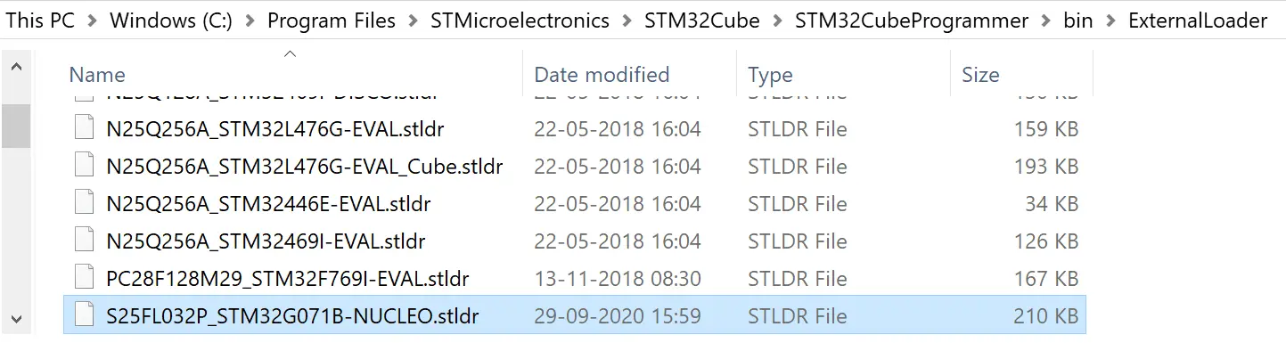
Copy flash loader to STM32CubeProgrammer installation
Now the flashloader can be selected in STM32CubeProgrammer as normal:
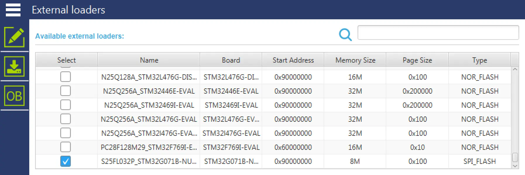
Copy flash loader to STM32CubeProgrammer installation
Tip
If a different GPIO configuration for the serial flash is used on custom hardware, the flash loader must be modified similarly.
Buttons
The button driver is very simple. It samples the state of the 5 GPIOs used for the joystick on MB1642B and the blue user button on the Nucleo board.
This button driver is installed as BottonController in TouchGFX. This means that the button presses are available directly in the TouchGFX Designer to use in interactions. They can also be used in user code like this:
void Screen1View::handleKeyEvent(uint8_t key)
{
    if (key == '6')
    {
        application().gotoScreen2Screen();
    }
}
The key codes used are:
| Key | Code |
|---|---|
| Left | '4' |
| Right | '6' |
| Up | '8' |
| Down | '2' |
| Center | '5' |
| Blue User Button | '0' |
These keys are also available in the Simulator bye using the keyboard numpad.