Lowering Memory Usage with Partial Framebuffer
This section explains, by exemplifying with a clock application, how to configure and use Partial Frame Buffers, to lower memory requirements at the expense of some performance.
A video of the application running on the STM32L4R9Discovery evaluation kit can be seen below
Full-size Frame Buffer Memory
Normally, your frame buffer is a big memory array with enough memory to hold all the pixels available on your display. If you are running on a 24-bit display with a resolution of 480 x 272, a full-size frame buffer holds 480 x 272 x 3 bytes = 391.680 bytes.
Some applications may have 2- ("Double buffering") or even 3 frame buffers. The total memory requirement in these cases would then be 783.360 and 1.175.040 bytes.
TouchGFX writes pixel values to the frame buffer when drawing any part of the UI, after all drawing operations have completed, the frame buffer is transferred to the display. Typically, the whole frame buffer is transferred to the display even if only a part of the UI is updated. Generally, the framebuffer can be updated in many small blocks before itis transferred.
Update1, Update 2, Update 3, ..., Update N, Transfer to display
In some cases, particularly in low cost solutions with no external RAM, frame buffers are required to be small enough to allow the rest of the application to fit in the internal RAM together with the framebuffer. This is where partial frame buffers are useful.
Partial Frame Buffer Memory
Partial frame buffers allows a TouchGFX application to run on top of a few, less than full-size frame buffers. The number and size of the frame buffers are configurable. This technique can lower the memory requirements of an application by a substantial amount, but comes with some limitations:
- Partial frame buffers will only work on displays that have built-in memory. These are typically DSI displays or displays with a parallel bus connection (DBI type A/B, 8080/6800) or SPI-bus connection.
- Potential tearing for complex applications.
Rather than using a frame buffer representing every pixel on the display, partial frame buffers typically cover a smaller part. In the clock example used in this article, three frame buffers of 11.700 bytes each are used. This results in a memory footprint for frame buffers of 35.100 bytes.
Whenever the application needs to update a part of the UI, TouchGFX will select one of the configured, partial frame buffers, complete its drawing operation in the partial framebuffer, and transfer that part to the display. This is repeated for all areas of the UI that need to be rendered - This changes the formula for updating and transferring data to:
Update1, Transfer1, Update2, Transfer2, Update3, Transfer3, ..., UpdateN, TransferN
In some cases the transfer of one partial frame buffer can run while the update of the next buffer is running.
Display Tearing
Contrary to using full-size frame buffers, TouchGFX will transfer parts of the UI as soon as they are updated, when using partial frame buffers. The display will show the received updates on its glass after at most 16 ms (for 60 fps displays) because the display needs to be refreshed regularly. Because of this, the first updates to the display can potentially be visible to the user before all updates have been transferred.
If the total sequence of draw operations and transfers take a long time to complete ( > 16 ms) it is highly possible that the user will see a combination of the previous frame and some of the new updates. This is called display tearing and is not desirable. For this reason, partial frame buffers are not suitable for applications that make use of complex animations that take a long time to render.
Display Update Example
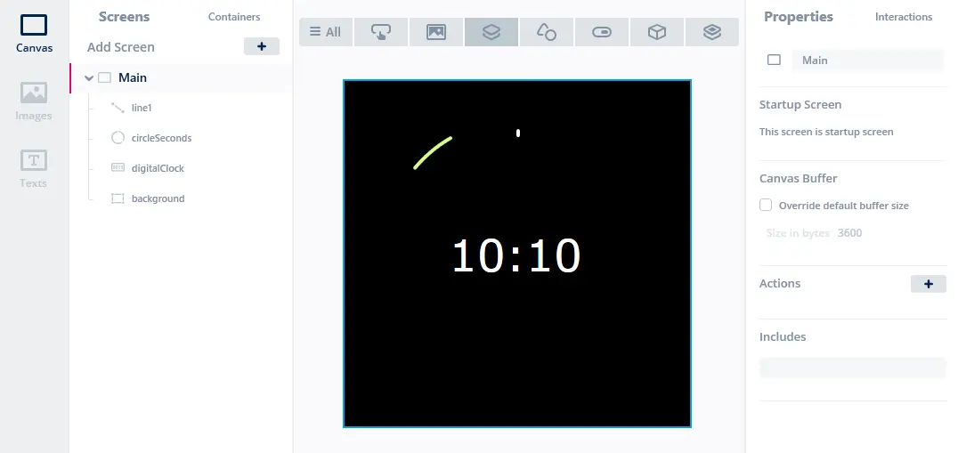
Before we get into how to configure partial frame buffers in your application let's have a look at a concrete example showing a digital clock with a moving circle arc representing seconds. The green circle arc is moving 6 degrees each second and does a full rotation in a minute. The UI is built from four Widgets as seen in the image below:
Here is the code that updates the digital clock and circle arc:
MainView.cpp
void MainView::handleTickEvent()
{
  ticks++;
  if (ticks == 10)
  {
      ticks = 0;
      secs += 1;
      if (secs == 60)  //increment minutes
      {
        secs = 0;
        min += 1;
        if (min == 60) //increment hours
        {
          min = 0;
          hour += 1;
          if (hour == 24)
          {
            hour = 0;
          }
        }
        //Only update digital clock when minutes or hours change
        digitalClock.setTime24Hour(hour, min, secs);
      }
    //Always update seconds
    circleSeconds.updateArc(secs*6 - 20, secs*6);
  }
}
The following images shows the areas that are updated in the first few seconds when the circle arc approaches the top and digital clock is updated (the grey rectangles). In the first two frames, only the seconds are changing (58 and 59 seconds). In the third the seconds reaches 60 and the hour and minutes text is updated:
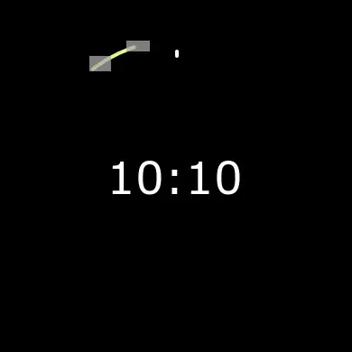
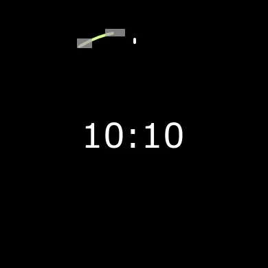

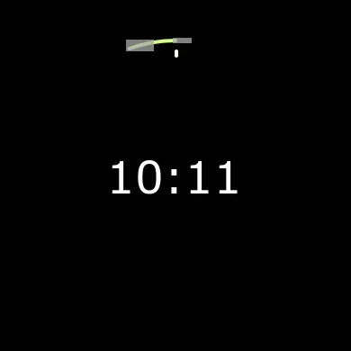
The rectangles updated in the third image above are 154 x 60 pixels, 20 x 12 pixels, and 33 x 8 pixels. When using standard frame buffers these three rectangles would be drawn into the full frame buffer (overwriting the previous pixels), which would afterwards be transferred to the display. When using partial frame buffers, these three rectangles would be drawn into their own little frame buffers which would then immediately be transferred to the display and shown.
Configuring Partial Frame Buffers
The following steps are required for TouchGFX to use partial frame buffers:
- Creating a frame buffer allocator object with a memory buffer
- Configuring TouchGFX HAL class to use that allocator
- Write code to transmit the buffers to the display
Steps 1 and 2 are automatically generated by TouchGFX Generator through STM32CubeMX while step 3 is a proprietary driver to transfer pixels to the display.
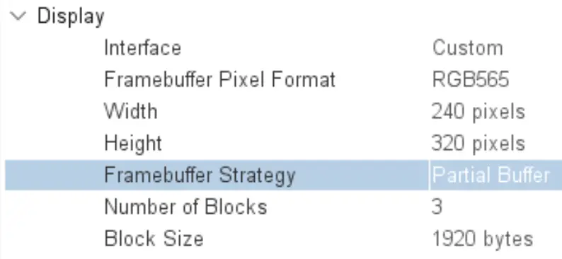
The above configuration generates the following code:
TouchGFXGeneratedHAL.cpp
// Block Allocator for Partial Framebuffer strategy
static ManyBlockAllocator<1920, /* block size */
                          3,    /* number of blocks */
                          2     /* bytes per pixel */
                          > blockAllocator;
This frame buffer allocator allocates 3 blocks, each 1920 bytes. TouchGFX HAL is automatically configured to use the Partial Framebuffer Strategy and to use the Block Allocator.
TouchGFXGeneratedHAL.cpp
void TouchGFXGeneratedHAL::initialize()
{
    HAL::initialize();

    registerEventListener(*(Application::getInstance()));
    enableLCDControllerInterrupt();
    enableInterrupts();
    // Partial framebuffer strategy
    setFrameBufferAllocator(&blockAllocator);
    setFrameRefreshStrategy(HAL::REFRESH_STRATEGY_PARTIAL_FRAMEBUFFER);
}
With this configuration TouchGFX will allocate small frame buffers and draw the UI in them. What is left now, is to transfer the small frame buffers to the display.
Lets first see the position and size of the two frame buffers allocated to draw the small circle updates (second image above):
| Rectangle | x | y | width | height | Pixels |
|---|---|---|---|---|---|
| Rectangle 1 | 112 | 56 | 22 | 14 | 308 pixels = 924 bytes |
| Rectangle 2 | 153 | 42 | 29 | 11 | 319 pixels = 957 bytes |
Both these rectangles are so small, they can fit into the blocks allocated by the frame buffer allocator.
In the third image above, we have 3 updated rectangles: The small updates to the circle, and the larger rectangle covering the text:
| Rectangle | x | y | width | height | Pixels |
|---|---|---|---|---|---|
| Rectangle 1 | 126 | 51 | 20 | 12 | 240 pixels = 720 bytes |
| Rectangle 2 | 165 | 42 | 33 | 8 | 264 pixels = 792 bytes |
| Rectangle 3 | 118 | 165 | 154 | 60 | 9.240 pixels = 27.720 bytes |
Again, the rectangle 1 and 2 are so small, they can fit into the blocks allocated by the frame buffer allocator, but frame buffer 3 is too large. This rectangle is to large and will be split into multiple rectangles that each can fit into the frame buffers (11.700 bytes).
Here the third rectangle to be updated is too big and will not fit into the last third block. In this situation TouchGFX will wait for the first blocks to be transferred and then reuse the blocks.
Transferring Frame Buffers to the Screen
TouchGFX will allocate a frame buffer from the FrameBufferAllocator, when a rectangle needs to be redrawn. After drawing to the buffer TouchGFX will call this method:
void HAL::flushFrameBuffer(const Rect& rect);
This function can be overridden in a HAL subclass to transfer the frame buffer to the screen. This special implementation is required for partial framebuffers to work. The following sections will illustrate how to configure this for the STM32G071 evaluation kit with a SPI displays, and the STM32L4R9Discovery evaluation kit which has a DSI display.
Transferring Frame Buffers to the X-NUCLEO-GFX01M1 SPI Display
In this section we will discuss the TouchGFX board setup for the STM32G071 nucleo board with the X-Nucleo-GFX01M1 expansion board. This expansion board, MB1642B, contains a 2.2" 240x320 SPI display and a 64-Mbit SPI NOR flash.
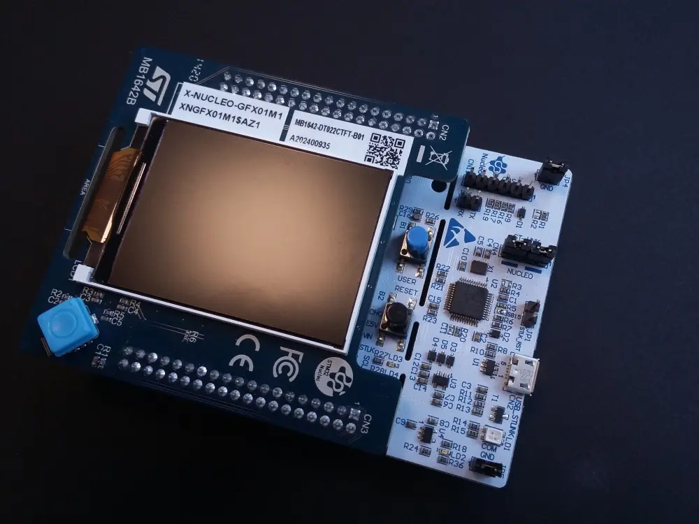
Nucleo-G071RB with X-Nucleo-GFX01M1 expansion board
In this TouchGFX board setup we use a C++ class from the framework to help managing the partial framebuffer blocks. This makes the code in the TouchGFX board setup a little shorter.
The TouchGFX board setup is build with the TouchGFX Generator. Read more about that here
The most important part is the flushFrameBuffer function:
TouchGFXGeneratedHAL.cpp
void TouchGFXGeneratedHAL::flushFrameBuffer(const touchgfx::Rect& rect)
{
    HAL::flushFrameBuffer(rect);
    // Try transmitting a block
    PartialFrameBufferManager::tryTransmitBlock();
}
Here we just call the PartialFrameBufferManager framework class to get the block transmitted.
In the TouchGFXGeneratedHAL::endFrame function we call PartialFrameBufferManager to get any remaining framebuffer blocks transmitted also:
TouchGFXGeneratedHAL.cpp
void TouchGFXGeneratedHAL::endFrame()
{
    // We must guard the next frame until we're done transferring all blocks over our display interface
    // through either a semaphore if user is running an OS or a simple variable if not
    PartialFrameBufferManager::transmitRemainingBlocks();

    HAL::endFrame();
    touchgfx::OSWrappers::signalRenderingDone();
}
The PartialFrameBufferManager uses three functions to interact with the display driver code. These must be implemented in the TouchGFX board setup:
TouchGFXGeneratedHAL.cpp
/**
 * Check if a Frame Buffer Block is beeing transmitted.
 */
__weak int transmitActive()
{
    return touchgfxDisplayDriverTransmitActive();
}

/**
 * Check if a Frame Buffer Block ending at bottom may be sent.
 */
__weak int shouldTransferBlock(uint16_t bottom)
{
    return touchgfxDisplayDriverShouldTransferBlock(bottom);
}

/**
 * Transmit a Frame Buffer Block.
 */
__weak void transmitBlock(const uint8_t* pixels, uint16_t x, uint16_t y, uint16_t w, uint16_t h)
{
    touchgfxDisplayDriverTransmitBlock(pixels, x, y, w, h);
}
The code above just forwards the calls to C functions in the MB1642B driver code.
MB1642BDisplayDriver.c
int touchgfxDisplayDriverTransmitActive(void)
{
  return IsTransmittingBlock_;
}

void touchgfxDisplayDriverTransmitBlock(const uint8_t* pixels, uint16_t x, uint16_t y, uint16_t w, uint16_t h)
{
  Display_Bitmap((uint16_t*)pixels, x, y, w, h);
}
The implementation of this driver code depends highly on the display used. For the MB1642B module this involves two GPIO to control SPI chip select and data/command mode.
The transmission state is implemented using a volatile uint8t variable *IsTransmittingBlock*. This variable is set to 1 when a transmission is started and set to zero in the DMA callback:
MB1642BDisplayDriver.c
void MB1642BDisplayDriver_DMACallback(void)
{
  /* Transfer Complete Interrupt management ***********************************/
  if ((0U != (DMA1->ISR & (DMA_FLAG_TC1))) && (0U != (hdma_spi1_tx.Instance->CCR & DMA_IT_TC)))
  {
    /* Disable the transfer complete and error interrupt */
    __HAL_DMA_DISABLE_IT(&hdma_spi1_tx, DMA_IT_TE | DMA_IT_TC);

    /* Clear the transfer complete flag */
    __HAL_DMA_CLEAR_FLAG(&hdma_spi1_tx, DMA_FLAG_TC1);

    IsTransmittingBlock_ = 0;

    ...

    // Signal Transfer Complete to TouchGFX
    DisplayDriver_TransferCompleteCallback();
As we see above, the DMA callback also calls the transfer complete callback. This function is implemented in the generated HAL:
TouchGFXGeneratedHAL.cpp
extern "C"
void DisplayDriver_TransferCompleteCallback()
{
    // After completed transmission start new transfer if blocks are ready.
    PartialFrameBufferManager::tryTransmitBlockFromIRQ();
}
The call to the PartialFrameBufferManager here makes it start a new transfer if possible.
Transferring Frame Buffers on DSI Display
The STM32L4R9Discovery evaluation kit uses a DSI display. The normal HAL class is called STM32HAL_DSI (located in STM32HAL_DSI.cpp).
We override the HAL::flushFrameBuffer method to notify the FrameBufferAllocator that a block has been drawn:
TouchGFXHAL.hpp
void TouchGFXHAL::flushFrameBuffer(const Rect& rect)
{
    frameBufferAllocator->markBlockReadyForTransfer();
    HAL::flushFrameBuffer(rect); //call normal implementation
}
The FrameBufferAllocator subclass ManyBlockAllocator will call the global function FrameBufferAllocatorSignalBlockDrawn() when a block is ready for transfer. This method must be implemented in the BSP layer:
TouchGFXGeneratedHAL.cpp
void FrameBufferAllocatorSignalBlockDrawn()
  {
    if (!dsiIsTransferring)
    {
      sendBlock();
    }
  }
This function is calling the sendBlock function, unless a transfer is already ongoing on the DSI. For the first block drawn by TouchGFX, this will never be the case, so a transfer is started. If another block drawing is completed while the DSI transfer is still running, the block will be kept in the "ready to transfer state", and drawing will continue in another free block (if available).
When a DSI transfer is completed, we must first free the transferred block, so it can be reused for another rectangle, and then check to see if the next block is ready for transfer. This is all done in the ER interrupt:
TouchGFXHAL.cpp
__irq void DSI_IRQHandler(void) {
  if (__HAL_DSI_GET_FLAG(&hdsi, DSI_IT_ER))
  {
    // End-of-refresh interrupt. Meaning last DSI transfer is complete
    __HAL_DSI_CLEAR_FLAG(&hdsi, DSI_IT_ER);
    if (dsiIsTransferring)
    {
      HAL::getInstance()->getFrameBufferAllocator()->freeBlockAfterTransfer();
      dsiIsTransferring = 0;
    }
    sendBlock(); //transfer next block if availble
  }
The function sendBlock is more complicated. Here we configure the LTDC and DSI peripherals to transfer the framebuffer. We also configure the display to put the transferred data into the correct place in the display memory. This part of the code is dependent on the specific display. Check the display datasheet for the command specifications.
TouchGFXHAL.cpp
static void sendBlock()
{
    FrameBufferAllocator* fbAllocator = HAL::getInstance()->getFrameBufferAllocator();

    //Is a block ready for transfer?
    if (fbAllocator->hasBlockReadyForTransfer())
    {
        Rect transfer_rect;
        const uint8_t* src = fbAllocator->getBlockForTransfer(transfer_rect);
        dsiIsTransferring = 1;

        //1. Setup LTDC and layer address and dimension
        //2. Configure display active area
        //3. Start DSI

        __HAL_DSI_WRAPPER_DISABLE(&hdsi);

        //1: Setup LTDC
        LTDC_Layer1->CFBAR = (uint32_t)src;

        const uint32_t width = transfer_rect.width;
        const uint32_t height = transfer_rect.height;

        LTDC->AWCR = ((width + 1) << 16) | (height + 1);
        LTDC->TWCR = ((width + 1 + 1) << 16) | (height + 1 + 1);

        const uint16_t layer_x0 = 2 + 0;
        const uint16_t layer_x1 = 2 + width - 1;
        LTDC_Layer1->WHPCR = (layer_x1 << 16) | layer_x0;

        const uint16_t layer_y0 = 2 + 0;
        const uint16_t layer_y1 = 2 + height - 1;
        LTDC_Layer1->WVPCR = (layer_y1 << 16) | layer_y0;

        LTDC_Layer1->CFBLR = ((width * 3) << 16) | (width * 3 + 3);
        LTDC_Layer1->CFBLNR = height;

        LTDC->SRCR = (uint32_t)LTDC_SRCR_IMR;

        //2: Configure display
        const int16_t x = transfer_rect.x + 4;
        const int16_t x2 = transfer_rect.x + 4 + width - 1;
        uint8_t InitParam1[4] = { (uint8_t)(x >> 8), (uint8_t)(x & 0xFF), (uint8_t)(x2 >> 8), (uint8_t)(x2 & 0xFF)};
        HAL_DSI_LongWrite(&hdsi, 0, DSI_DCS_LONG_PKT_WRITE, 4, DSI_SET_COLUMN_ADDRESS, InitParam1);

        const int16_t y = transfer_rect.y;
        const int16_t y2 = transfer_rect.y + height - 1;
        uint8_t InitParam2[4] = { (uint8_t)(y >> 8), (uint8_t)(y & 0xFF), (uint8_t)(y2 >> 8), (uint8_t)(y2 & 0xFF) };
        HAL_DSI_LongWrite(&hdsi, 0, DSI_DCS_LONG_PKT_WRITE, 4, DSI_SET_PAGE_ADDRESS, InitParam2);

        //3: Start DSI transfer
        __HAL_DSI_WRAPPER_ENABLE(&hdsi);
        HAL_DSI_Refresh(&hdsi);
    }
}
Transferring Frame Buffers on SPI Display
The principle for transferring the rectangles to the display is the same as for the DSI, but some details are different.
First, when a rectangle is drawn, we start a transfer if none is already in progress:
TouchGFXHAL.cpp
void TouchGFXHAL::flushFrameBuffer(const touchgfx::Rect& rect)
{
    HAL::flushFrameBuffer(rect);
    frameBufferAllocator->markBlockReadyForTransfer();
    //start transfer if not running already!
    if (!LCDManager_IsTransmittingData())
    {
        touchgfx::Rect r;
        const uint8_t* pixels = frameBufferAllocator->getBlockForTransfer(r);
        LCDManager_SendFrameBufferBlockWithPosition((uint8_t*)pixels, r.x, r.y, r.width, r.height);
    }
}
The function LCDManager_SendFrameBufferBlockWithPosition starts a SPI transfer to the display using DMA.
The SPI transfer complete handler calls a function when the transfer is complete:
TouchGFXHAL.cpp
void HAL_SPI_TxCpltCallback(SPI_HandleTypeDef *hspi)
{
    UNUSED(hspi);
    LCD_CS_HIGH();
    isTransmittingData = 0;

    //Change to SPI datasize to 8 bit from 16 bit
    heval_Spi.Instance->CR2 &= ~(SPI_DATASIZE_16BIT - SPI_DATASIZE_8BIT);

    //signal transfer complete
    LCDManager_TransferComplete();
}
The LCDManager_TransferComplete functions starts a new transfer:
TouchGFXHAL.cpp
void LCDManager_TransferComplete()
{
    touchgfx::startNewTransfer();
}

void startNewTransfer()
{
    FrameBufferAllocator* fba = HAL::getInstance()->getFrameBufferAllocator();
    fba->freeBlockAfterTransfer();
    blockIsTransferred = true;

    if (fba->hasBlockReadyForTransfer())
    {
        touchgfx::Rect r;
        const uint8_t* pixels = fba->getBlockForTransfer(r);
        LCDManager_SendFrameBufferBlockWithPosition((uint8_t*)pixels, r.x, r.y, r.width, r.height);
    }
}
Conclusion
In this article we saw how the partial frame buffer strategy can help lowering the memory requirements for platforms that have displays with integrated frame buffer memory.
The method for configuring and setting up partial framebuffers is the same across all platforms, but the method of sending the content of the blocks to the display varies. We saw how, for an LTDC/DSI based platform (STM32L4R9-DISCO) we were able to reconfigure the LTDC Layer to fit the next block ready for transfer on DSI, while on a platform with no LCD controller (STM32G071) we were able to send the blocks to the display using SPI.