Generator User Guide
TouchGFX Generator, a part of X-CUBE-TOUCHGFX, is a STM32CubeMX Additional-Software component that helps developers configure TouchGFX to run on their hardware platform. Based on existing STM32CubeMX settings and user input TouchGFX Generator will generate the files required to configure a working TouchGFX application. They include files for TouchGFX HAL, TouchGFX OSAL and TouchGFX Configuration.
Once code is generated through STM32CubeMX, the TouchGFX project can be opened through TouchGFX Designer where the UI is developed. TouchGFX Designer automatically adds any additional generated code files to the target IDE project that was configured for the project in STM32CubeMX.
Enabling TouchGFX Generator
Users gain access to adding functionality from X-CUBEs by pressing the "Select Components" button.
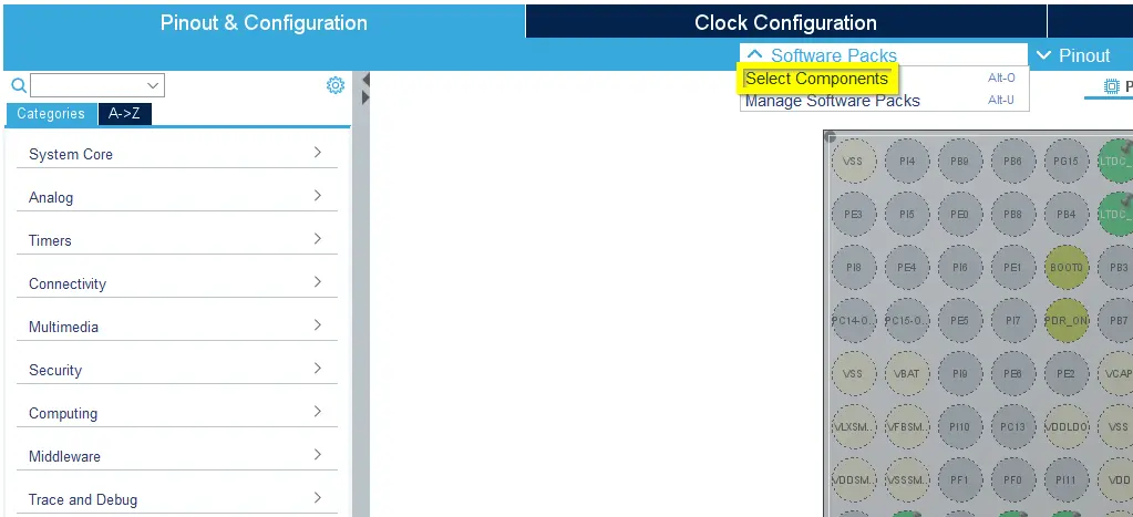
Selecting Additional Software in STM32CubeMX
The following figure shows how TouchGFX Generator can be enabled for a project:

Enabling TouchGFX Generator
If enabling TouchGFX for a Dual-Core MCU, be sure to enable for the the correct context. TouchGFX can only be enabled for a single context:
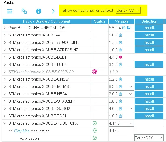
Enabling TouchGFX Generator for Dual Core
Generated Code Architecture
Before describing the features of TouchGFX Generator it is important to understand the architecture of the generated code and how developers can use it to customize configuration and behavior.
Handwritten user code in files generated by STM32CubeMX is protected through the use of User Code sections placed strategically throughout the code generated by STM32CubeMX (C code). In the code generated by TouchGFX Generator (C++ code) this flexibility is accomplished through inheritance.
When TouchGFX Generator is added through Additional Software and enabled, STM32CubeMX will always create a TouchGFX folder for the project. The folder always contains the same files, regardless of configuration, while the content of the files changes according to STM32CubeMX and User configuration.
The listing below shows an overview of the content of a STM32CubeMX project with TouchGFX Generator enabled, with emphasis on TouchGFX related files. The table following the list outlines the responsibility of the most important entries.
TouchGFX Folder
│   .mxproject
│   myproject.ioc
├───Core
├───Drivers
├───EWARM
├───Middlewares
└───TouchGFX
    │   ApplicationTemplate.touchgfx.part
    ├───App
    │       app_touchgfx.c
    │       app_touchgfx.h
    └───target
        │   STM32TouchController.cpp
        │   STM32TouchController.hpp
        │   TouchGFXGPIO.cpp
        │   TouchGFXHAL.cpp
        │   TouchGFXHAL.hpp
        │
        └───generated
                OSWrappers.cpp
                TouchGFXConfiguration.cpp
                TouchGFXGeneratedHAL.cpp
                TouchGFXGeneratedHAL.hpp
| Folder | Responsibility |
|---|---|
| myproject.ioc | STM32CubeMX Project file |
| Core | main.c and startup code |
| Drivers | CMSIS and MCU family drivers |
| EWARM | IDE project folder. Can be EWARM, MDK-ARM or STM32CubeIDE |
| Middlewares | Contains TouchGFX library/headerfiles and third party software like FreeRTOS. |
| ApplicationTemplate.touchgfx.part | The .part file is updated by STM32CubeMX with information that is relevant to TouchGFX Designer project, e.g. screen dimensions and bit depth |
| App | X-CUBE interface to STM32CubeMX. app_touchgfx.c contains definitions for the functions MX_TouchGFX_Process(void) and MX_TouchGFX_Init(void) which are used to initialize TouchGFX and start its main loop. |
| target/generated | This sub-folder contains the read-only files that get overwritten by STM32CubeMX when configurations change. TouchGFXGeneratedHAL.cpp is a sub-class of the TouchGFX class HAL and contains the code that STM32CubeMX can generate based on its current configuration. OSWrappers.cpp (The OSAL) contains the functions required to synchronize with TouchGFX Engine, and finally TouchGFXConfiguration.cpp which contains the code to construct and configure TouchGFX, including the HAL. |
| target | Contains the bulk of files that can be modified by the user to extend the behavior of the HAL or to override configurations generated by STM32CubeMX. STM32TouchController.cpp contains an empty touch controller interface. TouchGFXHAL.cpp defines a sub-class, TouchGFXHAL, of TouchGFXGeneratedHAL. |
It is important to know that TouchGFXConfiguration.cpp contains a function that constructs the HAL and a function that starts the main loop of TouchGFX. Additional configuration can be done in the editable user-class TouchGFXHAL. The general architecture of the HAL is seen below:
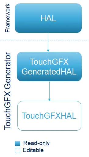
Hierarchy of generated code
Feature Overview
Having enabled TouchGFX Generator, four groups exist in the user interface:
- Dependencies - This group contains notifications to the developer about dependencies, warnings or concrete errors in the configuration. The group is hidden if no entries exist.
- Display - This group contains settings related to display such as interface, framebuffer bitdepth, width and height. These settings directly impact the size of the canvas of the TouchGFX project as well as the code generated for assets.
- Driver - This group allows the user to opt-in for a number of ready-made drivers related to the tick source of the application, graphics acceleration and RTOS. Since STM32CubeMX supports FreeRTOS (CMSIS RTOS v1 and v2) configurations, TouchGFX Generator provides drivers for each of these options.
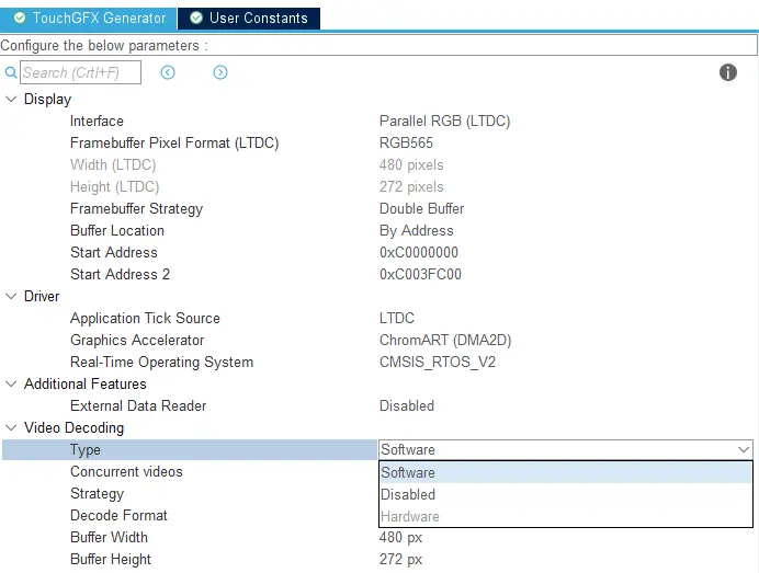
- Video Decoding - This group allows the user to enable hardware or software video decoding. This option is necessary to work with the video widget. Note that not all MCUs support video decoding.
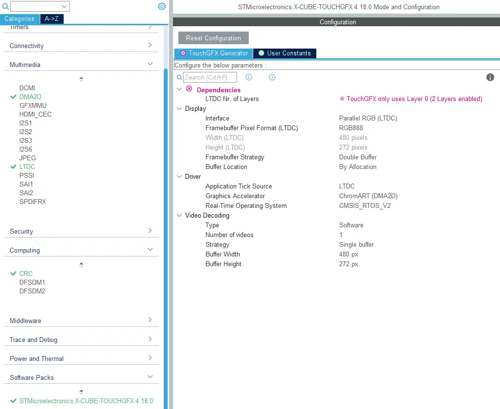
TouchGFX Generator has four groups: Dependencies, Display, Driver and Video Decoding
Display
The Display group contains configurations related to display, such as interface, dimensions and buffering strategies.
Interface and dimensions
Multiple display interfaces are usable today with STM32 microcontrollers, e.g.:
- Parallel RGB (LTDC)
- MIPI DSI
- FMC
- SPI
In the case of MCUs with a display connected to an LTDC or FMC TouchGFX Generator can generate code to transfer the framebuffer to the connected display. For DSI and SPI interfaces drivers must be implemented by developers themselves.
Further reading
Framebuffer Pixel Format
The following framebuffer pixel formats are currently supported by TouchGFX Generator. All options are available when using "Custom" display interface, otherwise options are restricted to display controller settings (e.g. configuring the LTDC Framebuffer format to "RGB565" will limit the options to "RGB565" in TouchGFX Generator).
- BW (1bpp)
- Grey2 (2bpp)
- Grey4 (4bpp)
- ABRG2222 (8bpp)
- ARGB2222 (8bpp)
- BGRA2222 (8bpp)
- RGBA2222 (8bpp)
- RGB565 (16bpp)
- RGB888 (24bpp)
- ARGB8888 (32bpp)
- XRGB8888 (32bpp)
Note
Caution
Further reading
Buffering Strategies
The following frame buffer strategies can be configured through TouchGFX generator:
- Single Buffer - Use only one application frame buffer. Possibly limits performance but uses less memory. Can be used with the "Buffer Location" configuration to place it in internal RAM. For further optimization the user can define a function that returns the current line being processed by the display controller. This method is used by the framework to allow updates to memory that has already been transferred to the display during this frame.
- Double Buffer - Use two frame buffers. Usually allows for better performance at the cost of memory.
- Partial Buffer - Use one or more user defined chunks of memory as the frame buffer. This strategy is targeted at low cost solutions that do not rely on external RAM, but have displays for which a full frame buffer would exceed available memory.
In the case of Single Buffer and Double Buffer users are allowed to configure their location through the "Buffer Location" configuration which offers the following options:
- By Allocation - Lets the linker place frame buffer memory according to linker script. Default is in internal RAM.
- By Address - Allows the user to define one (Single) or two (Double) frame buffer addresses.
The Partial Buffer strategy allows the user to define the following parameters:
- Number of blocks (always placed in internal RAM)
- Block size (bytes)
To understand some core concepts regarding the Partial Buffer strategy please read the dedicated article on Lowering Memory requirements using partial Frame Buffers. The article shows, conceptually, how to achieve partial frame buffers and the code shown in this article will differ slightly from what is generated by TouchGFX Generator. Please see Frame Buffer Strategies for concrete examples of the generated code for these strategies.
Driver
The driver section allows developers to select drivers for various responsibilities of a TouchGFX AL.
Application Tick Source
The application tick source for an application defines how to drive an application forward. The developer has the following options:
- LTDC - If LTDC is selected as the interface the "Display" group the Application Tick Source can be "LTDC". This means that TouchGFX Generator will install a driver function (LTDC interrupt handler) in
TouchGFXGeneratedHALclass that drives the application forward by callingOSWrappers::signalVSync(). - Custom and FMC - In this case, the developer is required to implement a handler that drives the application forward by calling
OSWrappers::signalVSync()repeatedly.
Graphics Accelerator
The developer has three options when it comes to graphics acceleration:
- None - The application uses only the CPU to render frames.
- Chrom-ART (DMA2D) - The application uses the Chrom-ART chip when possible to move and blend pixels, freeing up CPU cycles. The driver is installed by TouchGFX Generator and does not require any action from the developer.
The Chrom-ART (DMA2D) driver supplied by TouchGFX Generator supports two ways of receiving a TransferCompleteInterrupt.
- Uses the STM32Cube HAL driver where it registers a callback funtion to the dma2d handle
hdma2d.XferCpltCallback. - Uses the
DMA2D_IRQHandler()interrupt handler directly.
Switching between these two is done by enabling or disabling the DMA2D global interrupt in the NVIC Settings in STM32CubeMX for DMA2D IP. Enabling the global interrupt generated code for option 1), disabling the global interrupt generates code for option 2).
Note
Real-Time Operating System
Developers can use any RTOS with TouchGFX (even No OS). As described in the Abstraction Layer Architecture the TouchGFX Engine uses the OSWrappers interface to synchronize its main event loop as well as framebuffer access with the users choice of RTOS. When developers select an operating system via TouchGFX Generator code will be generated to syncronize internally via primitives for the OS of choice. The operating system still has to be configured through STM32CubeMX to determine stack size, among other things.
FreeRTOS (CMSIS OS compliant) and AzureRTOS (For H7s only) can be configured directly from within STM32CubeMX and the TouchGFX Generator providing the user with generated code for both task definitions and TouchGFX RTOS driver. TouchGFX Generator can generate CMSIS V1 and CMSIS V2 compliant RTOS drivers which work with any CMSIS compliant RTOS, a driver for running bare metal without an operating system, and a native driver for ThreadX (Through the AzureRTOS X-Cube). In the case of No Operating Systemn developers cannot rely on STM32CubeMX for code generation of task definitions and this must be done in user code.
Note
The following figure shows these options available through the TouchGFX Generator.
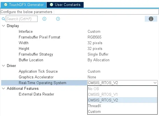
RTOS driver options
Concretely, in this image, The AzureRTOS X-CUBE has been enabled, allowing the selection of ThreadX and CMSIS RTOS V2 (ThreadX is CMSIS compliant). If FreeRTOS is enabled the "ThreadX" option is disabled. ThreadX can be enabled through the X-CUBE-AZRTOS-H7 (H7 only) pack.
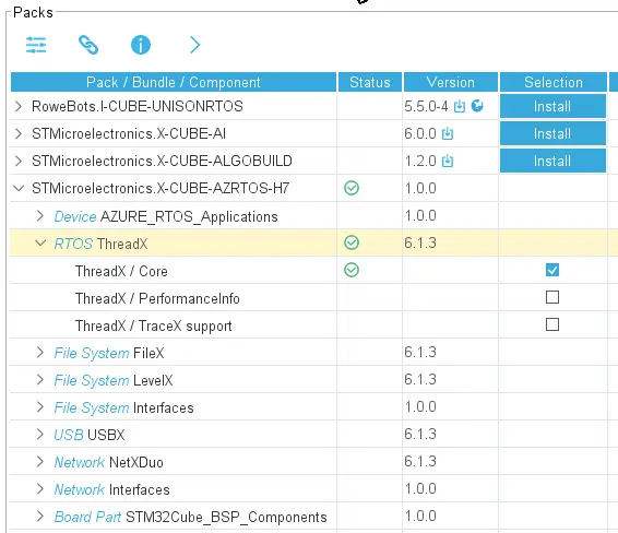
X-CUBE-AZRTOS Configuration
The TouchGFX main loop is entered when calling the following function.
void MX_TouchGFX_Process(void);
Developers are required to call this function in the task handler for the task they intend to run the TouchGFX application in. If the user configured a FeeRTOS task from STM32CubeMX called DefaultTask then the following example shows how MX_TouchGFX_Process() is called to start TouchGFX in the user code section of its task handler.
void StartDefaultTask(void *argument)
{
  /* USER CODE BEGIN 5 */
  MX_TouchGFX_Process();
  /* USER CODE END 5 */
}
When FreeRTOS is enabled, STM32CubeMX will also generate a call to osKernelStart(); which starts the scheduler.
Other CMSIS compliant OS
When developers require a different CMSIS compliant OS than what STM32CubeMX can offer (FreeRTOS and ThreadX) he must perform RTOS configuration and task definition manually. Generally, the following manual steps are required:
- Configure the RTOS
- Define a task to run TouchGFX (
MX_TouchGFX_Process) - Start the scheduler
Here's an example of how to perform steps 2 and 3 for ThreadX, manually. Since STM32CubeMX cannot help with any configuration for operating systems it does not support everything must be done in the provided user code sections to avoid code being overwritten. The following code shows pseudo code for the GUI task definition. Generally, any code that is not generated by STM32CubeMX should be placed in user code sections that are scattered throughout the file main.c.
/* BEGIN USER CODE SECTION */
#include "tx_api.h"

#define GUI_THREAD_STACK_SIZE         1024
TX_THREAD gui_thread;
void    gui_thread_entry(ULONG thread_input); //Thread prototype
/* END USER CODE SECTION */

int main()
{
  /* BEGIN USER CODE SECTION - Choose an appropriate one from main.c */
  /* Allocate the stack for gui thread  */
  tx_byte_allocate(...);

  /* Create the gui thread.  */
  tx_thread_create(&gui_thread, "GUI Thread", gui_thread_entry, 0,
              pointer, GUI_TASK_STACK_SIZE,
              1, 1, TX_NO_TIME_SLICE, TX_AUTO_START);

  /* END USER CODE SECTION*/
Call MX_TouchGFX_Process to start the TouchGFX Engine Main Loop inside the task handler.
/* BEGIN USER CODE SECTION */
void gui_thread_entry(ULONG thread_input)
{
  MX_TouchGFX_Process();
}
/* END USER CODE SECTION*/
Start the scheduler to start the GIU task and your TouchGFX Application.
/* BEGIN USER CODE SECTION */
tx_kernel_enter();
/* END USER CODE SECTION*/
Additional features
External Data Reader
For the RGB565 Framebuffer Pixel Format touchgfx supports a so called Data Reader interface that allows developers to read data directly from a non-memory-mapped serial flash instead of caching which comes at the cost of an additional buffer in memory. Please see the SerialFlash article for a example on how to implement a DataReader to retrieve application assets from a non-memory mapped flash chip.
The Data Reader option is typically used for low cost solutions (e.g. STM32G0) that do not have enough memory for additional buffers. It cannot be enabled if DMA2D is also enabled.
Once RGB565 is selected as the Framebuffer Pixel Format, Additional Features group becomes available.
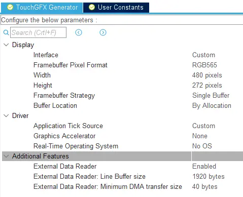
Additional Features: Data Reader
The following configurations can be made by the developer:
- External Data Reader: Enable or Disable the feature. Enabling will cause TouchGFX to retrieve data for assets directly through the generated interface. If disabled, developers are then required to cache images to a buffer in memory instead.
- External Data Reader: Line Buffer Size: Creates two buffers for blending images or text into the framebuffer. Default value is one screen width*4 bytes to support full size images in ARGB8888 pixel format.
- External Data Reader: Minimum DMA transfer size: Set minimum required bytes to start a DMA transfer. If fewer bytes are requested, DMA will not be used.
After generating code with External Data Reader enabled, the following, additional files are created to support the retrieval of assets directly from a non-memory mapped flash.
TouchGFX/target/generated/TouchGFXGeneratedDataReader.cppTouchGFX/target/generated/TouchGFXGeneratedDataReader.hppTouchGFX/target/TouchGFXDataReader.cppTouchGFX/target/TouchGFXDataReader.hpp
As usual, for code generated by TouchGFX Generator, TouchGFXGeneratedDataReader is read-only and user modifications should be made inside the TouchGFXDataReader class. TouchGFXGeneratedDataReader is of type touchgfx::FlashDataReader.
Modifications will be made to the following files to configure TouchGFX HAL to use the DataReader.
TouchGFX/target/generated/TouchGFXConfiguration.cppTouchGFX/target/generated/TouchGFXGeneratedHAL.cppTouchGFX/target/generated/TouchGFXGeneratedHAL.hpp
Note
8bit LTDC Color Look-up Table
When the LTDC is configured to read the framebuffer in L8 format and TouchGFX renders in either ABRG2222, ARGB222, BGRA2222, or RGBA2222, TouchGFX Generator will provide a CLUT which is loaded into the LTDC during TouchGFXHAL::initialize(). Please refer to the STM32 MCU reference manual for more details on usage of LTDC and CLUT.
Video Decoding
The Video Decoding section allows developers to enhance the TouchGFX HAL with either hardware or software video decoding capabilities.
Video Decoding is only available with RGB565 (16bpp) and RGB888 (24bpp) framebuffer pixel formats. If neither of these formats are selected the Video Decoding section will not be available.
Note
Type
By default the "Type" of video Decoding is disabled. If the required peripherals are not enabled in STM32CubeMX both "Software" and "Hardware" will be greyed out. Hover the mouse over the greyed out options the see which peripherals are required.
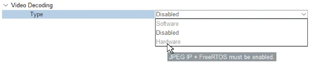
Info box showing Video Type dependencies for "Hardware"
- Software - If LIBJPEG is enabled under the Middleware section in STM32CubeMX the "Software" option can be selected and the software decoder will be generated. This means that TouchGFX Generator will generate a software MJPEG decoder.
- Hardware - If JPEG is enabled under the Multimedia section and a CMSIS compliant RTOS is selected in the TouchGFX Generator the "Hardware" option can be selected.
Video decoding type options
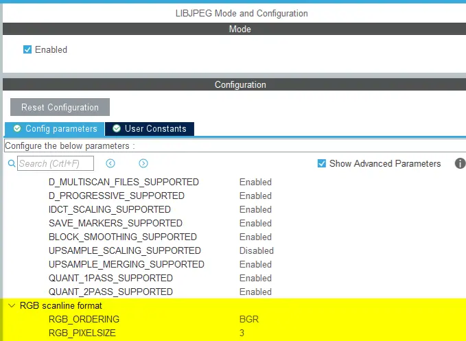
In the LIBJPEG settings the RGB ordering in the "RGB scanline format"-section has to be set to "BGR" instead of "RGB" for efficiency. The number of bytes per pixel must be set to 3.
Required LIBJPEG RGB scanline format settings
When working with hardware decoding the RGB format in the JPEG settings has to be the same as the display.
Further reading
Concurrent videos
The "Concurrent Videos" option is the largest amount of videos being decoded simultainously on the same screen in the GUI at any given time. If you only wish to decode one video on a screen the "Number of Videos" can be set to 1.
A maximum of 4 videos can be decoded simultaneously.
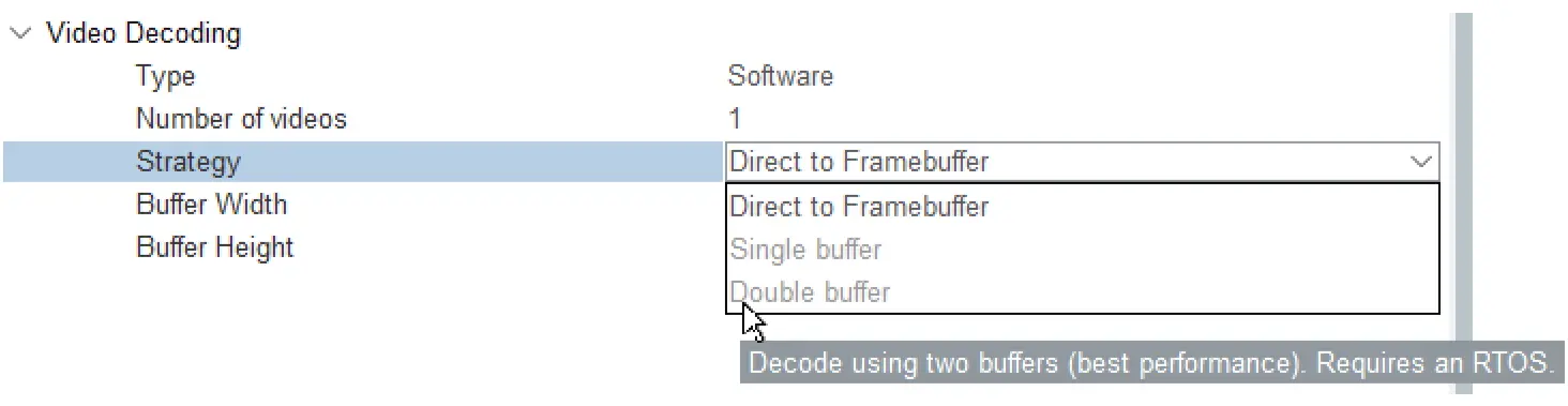
Strategy
The developer has three options when it comes to the video decoding strategy.
- Direct to Framebuffer - The video is decoded in the UI thread. It is slower than the other strategies. When working with hardware video decoding the "Direct to Framebuffer" option is unavailable.
- Single Buffer - Video is decoded in a seperate task in a dedicated buffer. This buffer is allocated in internal memory.
- Double Buffer - Video is decoded in a seperate task in two dedicated buffers for better performances at the cost of memory.
When working with the single or double framebuffer strategy it is necessary to enable a CMSIS compliant OS.
Info box about CMSIS RTOS requirement
Note
Further reading
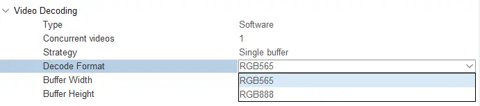
Decode Format
For Software decoding, developers can choose the pixel format of the RGB buffer regardless of the pixel format of the framebuffer. TouchGFX Generator generates code that allows ChromART to do pixel-format-conversion between the formats if they're different. Having the video decoding buffer in RGB565 allows developers to have a smaller memory footprint.
Decode format
Buffer size
The buffer width and height settings must correspond to the largest video dimension in the application. The width must be divisible by 32.
The following code is the generated code in TouchGFXGeneratedHAL.cpp for an application using an RGB888 display with a 480*272 video and the "Single Buffer" video decoding strategy.
TouchGFXGeneratedHAL.cpp
#include <DedicatedBufferVideoController.hpp>
#include <SoftwareMJPEGDecoder.hpp>

uint32_t lineBuffer[480];

SoftwareMJPEGDecoder mjpegdecoder1((uint8_t*)lineBuffer);

uint32_t videoRGBBuffer[97920];
DedicatedBufferController<1, 480, 272, 480*3U, Bitmap::RGB888> videoController;

//Singleton Factory
VideoController& VideoController::getInstance()
{
    return videoController;
}

void TouchGFXGeneratedHAL::initialize()
{
    HAL::initialize();
    registerEventListener(*(Application::getInstance()));
    setFrameBufferStartAddresses((void*)frameBuf, (void*)(frameBuf + sizeof(frameBuf) / (sizeof(uint32_t) * 2)), (void*)0);

    /*
     * Add software decoder to video controller
     */
    videoController.addDecoder(mjpegdecoder1, 0);

    videoController.setRGBBuffer((uint8_t*)videoRGBBuffer, sizeof(videoRGBBuffer));
}
Generated project
TouchGFX works with (at least) the following IDEs when generating code using the Generate Code button in STM32CubeMX:
- EWARM
- MDK-ARM
- STM32CubeIDE
For optimal project structure select the following options for project generation:
- Application structure: Advanced
- Disable Generate under root (STM32CubeIDE only)
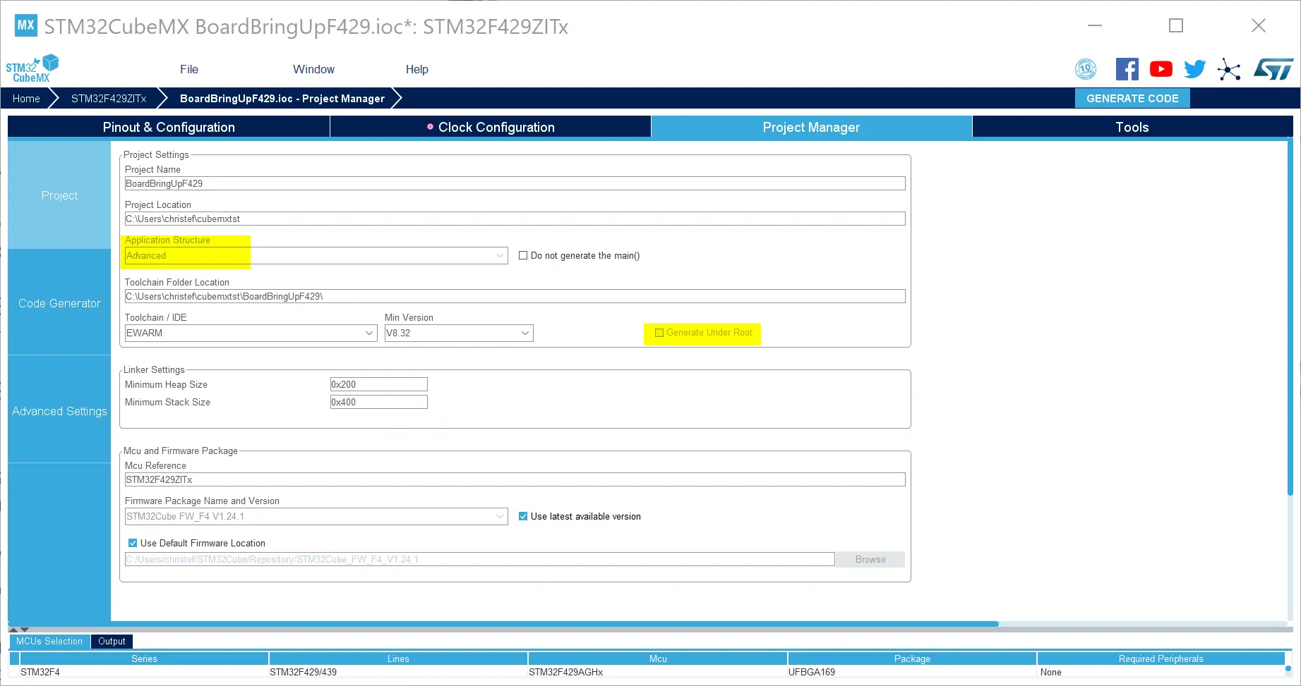
Select Advanced application structure and deselect Generate under root
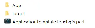
STM32CubeMX will also generate a TouchGFX folder with the following structure:
TouchGFX folder structure
- The App folder which contains code to initialize and start TouchGFX.
- The target folder which contains read-only, generated code (inside generated/) and modifiable user classes (
STM32TouchController.cpp,TouchGFXGPIO.cppandTouchGFXHAL.cpp) - The .part file which is opened using the TouchGFX Designer in order to create a full TouchGFX project complete with TouchGFX header files and libraries The part file contains relevant application information such as pixel format, and canvas dimensions that the designer uses when generating TouchGFX application code.
TouchGFX Designer Project
The following code is an example of the contents of the .part file mentioned in the Generated Code Architecture section. The post-generate command, seen below, will update the project selected in STM32CubeMX (e.g. EWARM) when new files are created by the TouchGFX designer (e.g. new screens and assets).
{
 "Application": {
 "Name": "my_project",
 "TouchGfxPath": "../Middlewares/ST/touchgfx",
 "AvailableColorDepths": [ 16 ],
 "AvailableLCDs":
  {
    "16": "LCD16bpp"
 },
 "AvailableResolutions" :
 [
  {
    "Width": 320,
    "Height": 240
  }
 ],
 "PostGenerateTargetCommand" : "touchgfx update_project --project-file=../my_project.ioc --platform=m7"
 },
 "Version": "4.13.0"
}
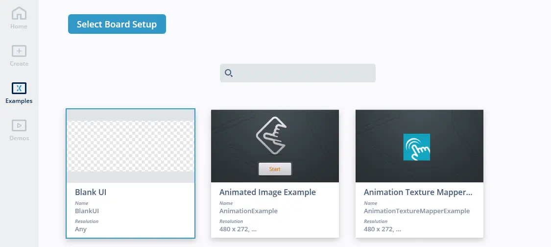
When opening the .part file with TouchGFX Designer developers are presented with the option to load a concrete UI or start from a blank template.
Choose UI
After pressing Generate Code in TouchGFX Designer the structure of the TouchGFX folder now looks like the following. The following image shows a concrete example of a TouchGFX folder structure and highlights the files and folders that are new after generation.

Generate Code
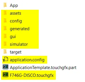
TouchGFX Folder Structure
TouchGFX will detect the selected IDE from the .ioc STM32CubeMX file (For STM32CubeIDE, EWARM, MDK-ARM) and update the project file with new, generated files like files for screen definitions, image- and font assets.
At this point, developers can work interchangeably in STM32CubeMX, TouchGFX Designer and toolchain/IDE where:
- STM32CubeMX updates the IDE project with drivers
- STM32CubeMX updates the TouchGFX .part file with UI related changes that are instantly picked up by the designer
- STM32CubeMX generates HAL code (TouchGFX/target/generated/) based on TouchGFX Generator Configuration necessary for TouchGFX to work on a specific platform.
- The TouchGFX designer updates the project with generated code.
Note
Modifying Generated Behavior
It important to know that, due to the class hierarchy of the HAL, users can override HAL configuration or behavior that was generated by STM32CubeMX. In the example below, developers can modify the initialize function to configure TouchGFX additionally or to modify an existing configuration set in TouchGFXGeneratedHAL.
TouchGFXHAL.cpp
void TouchGFXHAL::initialize()
{
    // Calling parent implementation of initialize().
    //
    // To overwrite the generated implementation, omit call to parent function
    // and implemented needed functionality here.
    // Please note, HAL::initialize() must be called to initialize the framework.

    TouchGFXGeneratedHAL::initialize();

    //Overriding configurations
    hal.lockDMAToFrontPorch(true);
    hal.setFingerSize(4);
    hal....
}
Upgrading Projects
TouchGFX Generator parameters are stored in .ioc files (STM32CubeMX project). When a new version of TouchGFX Generator is released the parameters of the old version may be incompatible with the new version and may require migration.
Since STM32CubeMX does not support upgrading between X-CUBE versions the upgrade is automatically performed by TouchGFX Designer when Generate Code is pressed due to the following command in the PostGenerateTargetCommand section of the .touchgfx file.
.touchgfx
"PostGenerateTargetCommand" : "touchgfx update_project --project-file=../upgrade.ioc --platform=m7"
The command will read the .ioc file and update the parameters to fit the current version of X-CUBE-TOUCHGFX. Below is an example of running the script (X-CUBE-TOUCHGFX 4.14.0) by hand on an .ioc file created with X-CUBE-TOUCHGFX 4.13.0.
Upgrade example using STM32F746 DISCO TouchGFX Board Setup from 4.13.0 to 4.14.0
$ touchgfx update_project --project-file=../STM32F746G_DISCO.ioc
  TouchGFX Generator 4.13.0 found
  Creating backup of ../STM32F746G_DISCO.ioc as ../backup_STM32F746G_DISCO.ioc
  Performing upgrade 4.13.0 -> 4.14.0 ... OK
Opening the updated project with STM32CubeMX prompts the user to install the version of X-CUBE-TOUCHGFX that is represented by the .ioc file (if not already installed). Clicking Download now will download and install X-Cube-TouchGFX-4.14.0.
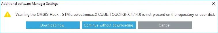
Additional Software Component Missing: TouchGFX Generator 4.14.0
All configurations in TouchGFX Generator will be kept during the upgrade procedure and a backup of the .ioc file will be placed beside the original on prepended with backup_.