3. Display with framebuffer in internal RAM
Motivation
In this step we will see the display come to life by transferring pixel data from the internal RAM to the display. This step ensures that we can transmit data to the display and that we can continuously update the contents of the display.
In addition to transferring image data to the display we must also make sure that we can continuously send new data to the display without seeing errors on the display. We are also going to measure the speed of the transfer as this has influence on the frame rate we can obtain with the display.
We will place a framebuffer in internal RAM as we know from last section that this RAM is both readable and writable. We will update and transfer this framebuffer to the display repeatedly.
Recall that the size of the framebuffer is calculated by this formula:
width x height x bpp
So, for example, a common 16 bit display with resolution 480 x 272 will take up 480x272x16/8 bytes = 261120 bytes.
If the display size implies a framebuffer too large to be stored in internal RAM, you should not skip this step. Instead configure the display controller to only update a part of the display. This way we can tune the amount of RAM needed for the framebuffer and make it fit internal RAM.
The type of display interface has a large impact on the setup and code needed to transfer the framebuffer. In this section we will first target a display connected to the LTDC. If you are using e.g. a SPI display, the code will be very different, but the tasks and goals are the same.
Goal
The goal in this section is to transfer a framebuffer to the display. You should also verify that you can modify the framebuffer content and resend the framebuffer continuously.
Verification
Here are the verification points for this section:
| Verification Point | Rationale |
|---|---|
| Framebuffer is shown | Display controller or SPI is configured and running |
| Updated framebuffer is shown | We know how to repeatedly transmit the framebuffer |
| Colors are correct | The GPIOs are correct (LTDC) and the data format of the display matches our framebuffer |
| Framerate is correct | The pixel clock and porches are configured to get the required framerate |
Prerequisites
The following are the prerequisites for this step:
- Information about the display, typically a datasheet
- Information about the connections between the MCU and the display.
Do
Depending on the display type, the needed setup differs. But for all display types we need a framebuffer in internal RAM. An easy way to allocate that memory is to just declare a global array with the correct size:
main.c
/* USER CODE BEGIN PV */
uint16_t framebuffer[480*272];  //16 bpp framebuffer
/* USER CODE END PV */
If your internal RAM is not big enough to hold the array, declare a array corresponding to a smaller resolution, say 480x200.
The method to transfer the framebuffer to the display depends on the display type. We will look at this now.
Caution
Therefore, the RAM start address must be changed beforehand. This can be done by modifying the linker script. You can find the usable memory addresses and additional details in your chip’s datasheet.
Parallel RGB Displays
We will first discuss a parallel RGB display connected to the LTDC controller on the MCU.
The configuration tasks for a display like this are:
- Configure the GPIO connections to the display
- Configure the LTDC controller
- Configure the LTDC pixel clock
- Setting the framebuffer address
- Check the framerate
As an illustrative example we will use a STM32F746Discovery evaluation kit. This board features a 480*272 display.
Display GPIO
This display is running in 24 BPP mode, so we configure the 24 GPIOs for the connection between the LTDC and the display. This is most easily done in STM32CubeMX under Multimedia -> LTDC -> GPIO Settings:
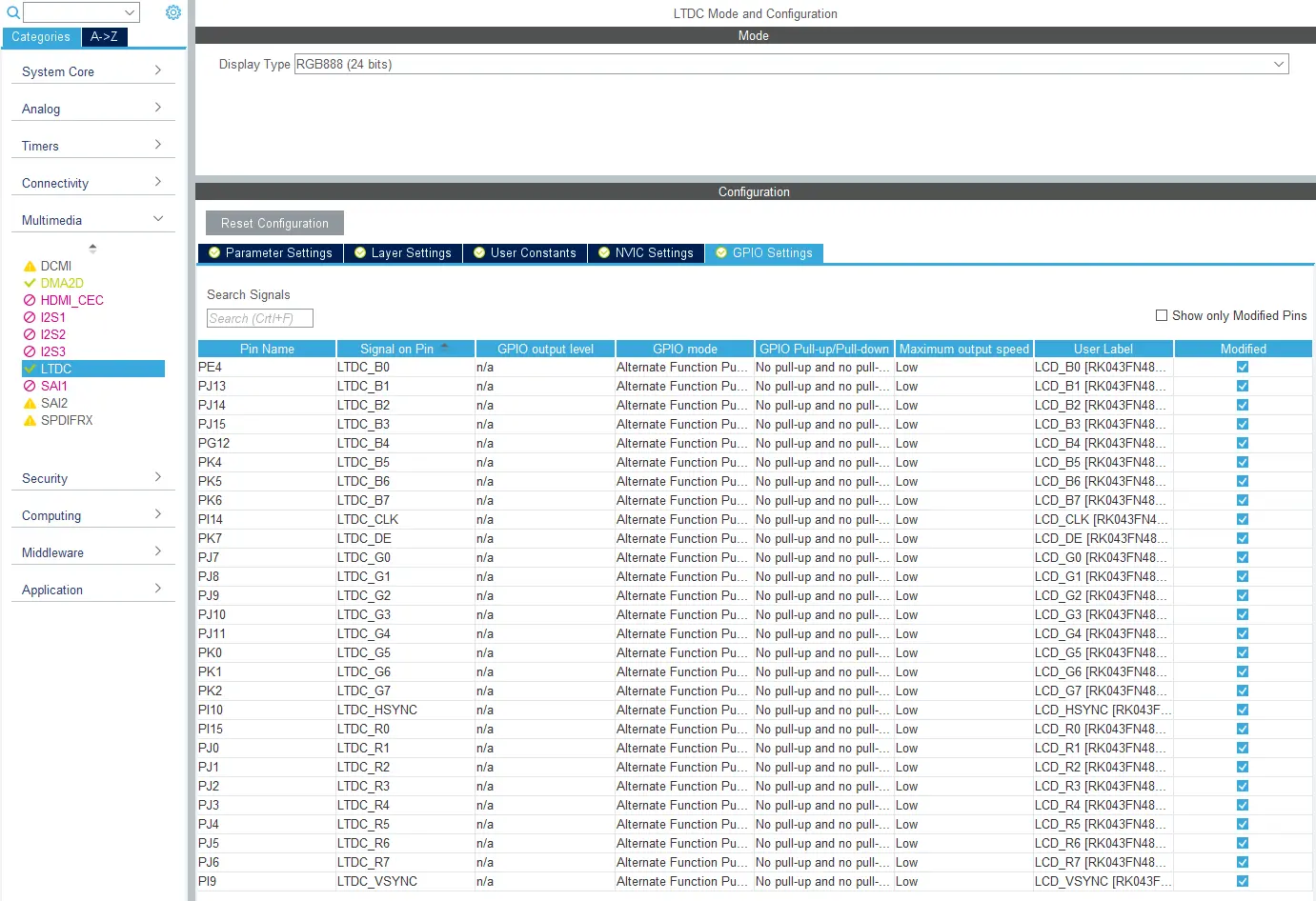
Configuring display GPIOs
Besides the 24 GPIOs for the pixel transfer (e.g. LTDC_B0) we also configure the 4 display control signals:
| Signal | Function |
|---|---|
| LTDC_CLK | Pixel clock. Signals to the display when to sample the pixels from the 24 lines |
| LTDC_DE | Data enable. Pixels are transferred when active |
| LTDC_HSYNC | Horizontal synchronisation. Allows the display to find the pixel line start |
| LTDC_VSYNC | Vertical synchronisation. Allows the display to find the frame start |
Check your hardware design and make the corresponding configurations.
LTDC Configuration
The LTDC configuration is found in STM32CubeMX under Multimedia -> LTDC -> Parameter Settings:
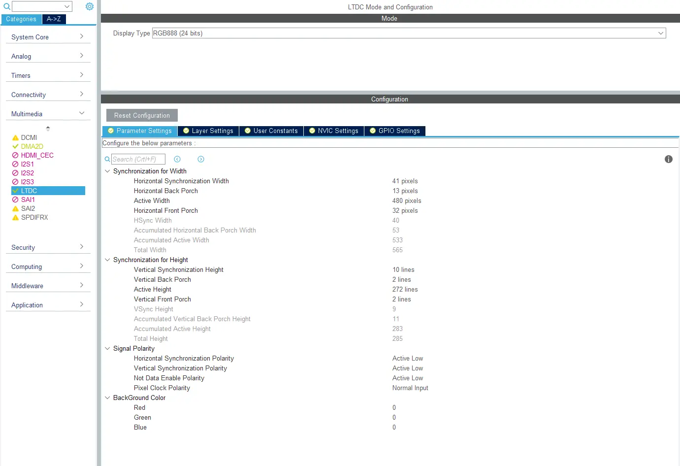
Configuring LTDC Parameters
The active width and height corresponds to the resolution of your display. Check your display datasheet for the synchronization pulse widths and the porch widths. Also pay attention to the signal polarities. The values shown in grey are computed from the other values. These values are written to the LTDC registers (and can be found in the code).
Now go to the LTDC Layer configuration under Multimedia -> LTDC -> Layer Settings:
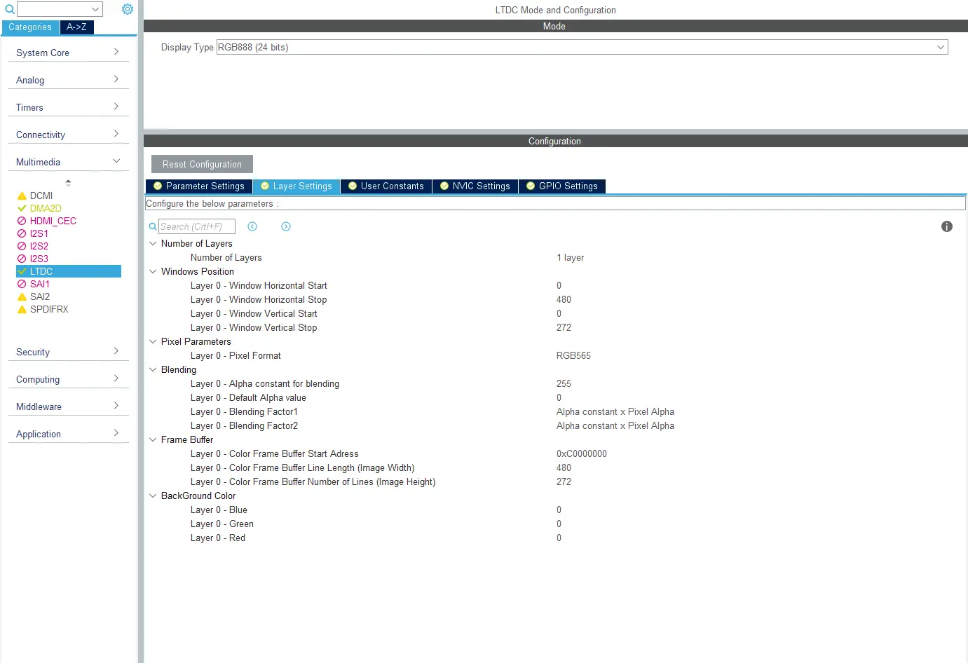
Configuring LTDC Layer Parameters
For this test and in TouchGFX in general we will only use one layer. The resolution of Layer 0 should match the framebuffer dimension. The framebuffer address needs to be set later, so just leave the address unchanged here.
If you declared a framebuffer array smaller than the display resolution, then adjust the layer size to match the framebuffer dimension. The LTDC will transmit the background color for the display pixels not available in the framebuffer. It is recommended to set the background color (in the Parameter Settings tab) to something recognisable like red (Blue: 0x00, Green: 0x00, Red: 0xFF).
Clock Configuration
The clock configuration is also important. The clock must be enabled for all the GPIOs and the LTDC. The pixel clock must be in the range acceptable by the display.
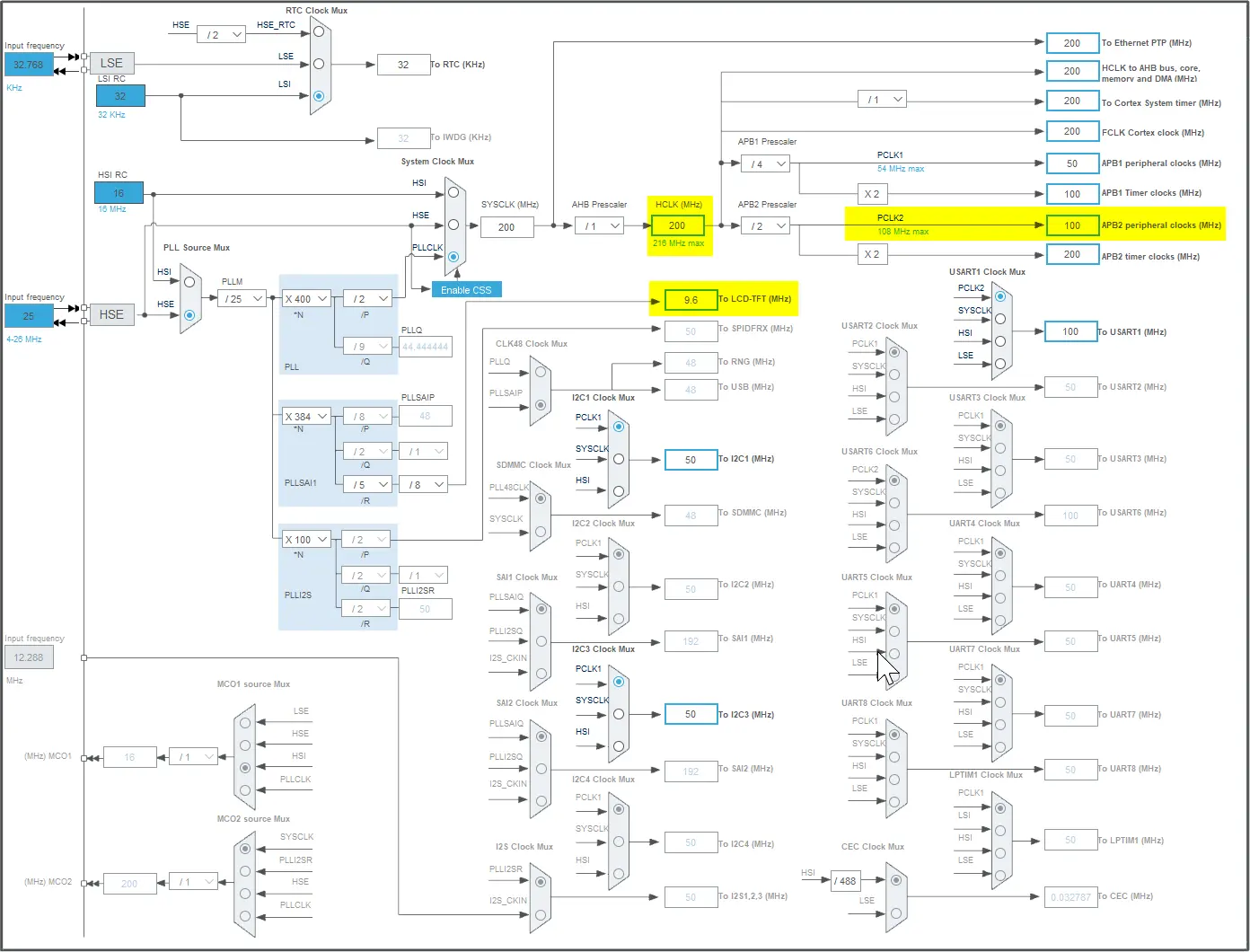
Clock configuration
The LTDC depends on 3 clocks: HCLK, PCLK2, and LCD_CLK.
Setting the Framebuffer Address
In STM32CubeMX we configured the framebuffer address of layer 0 to 0xC0000000. We need to change that to the address of our array in internal RAM. This is easily done by using one of the STM32Cube Firmware HAL functions:
main.c
  /* USER CODE BEGIN 2 */
  HAL_LTDC_SetAddress(&hltdc, (uint32_t)framebuffer, LTDC_LAYER_1);
  /* USER CODE END 2 */
Layers are numbered 1, 2, in the HAL functions, but 0, 1 in STM32CubeMX. The LTDC is otherwise fully configured by the code generated by STM32CubeMX in the function MX_LTDC_Init(void).
The LTDC controller transmits the framebuffer to the display repeatedly. The image displayed depends on the values in the framebuffer. Try different values or patterns in the framebuffer. Use e.g. memset to clear the framebuffer to 0xFF to get a white display.
Note
Enabling LTDC interrupt
The LTDC controller raises an interrupt for each frame, this interrupt must be enabled in the NVIC (core interrupt controller) to be able to handle the interrupt in your application.
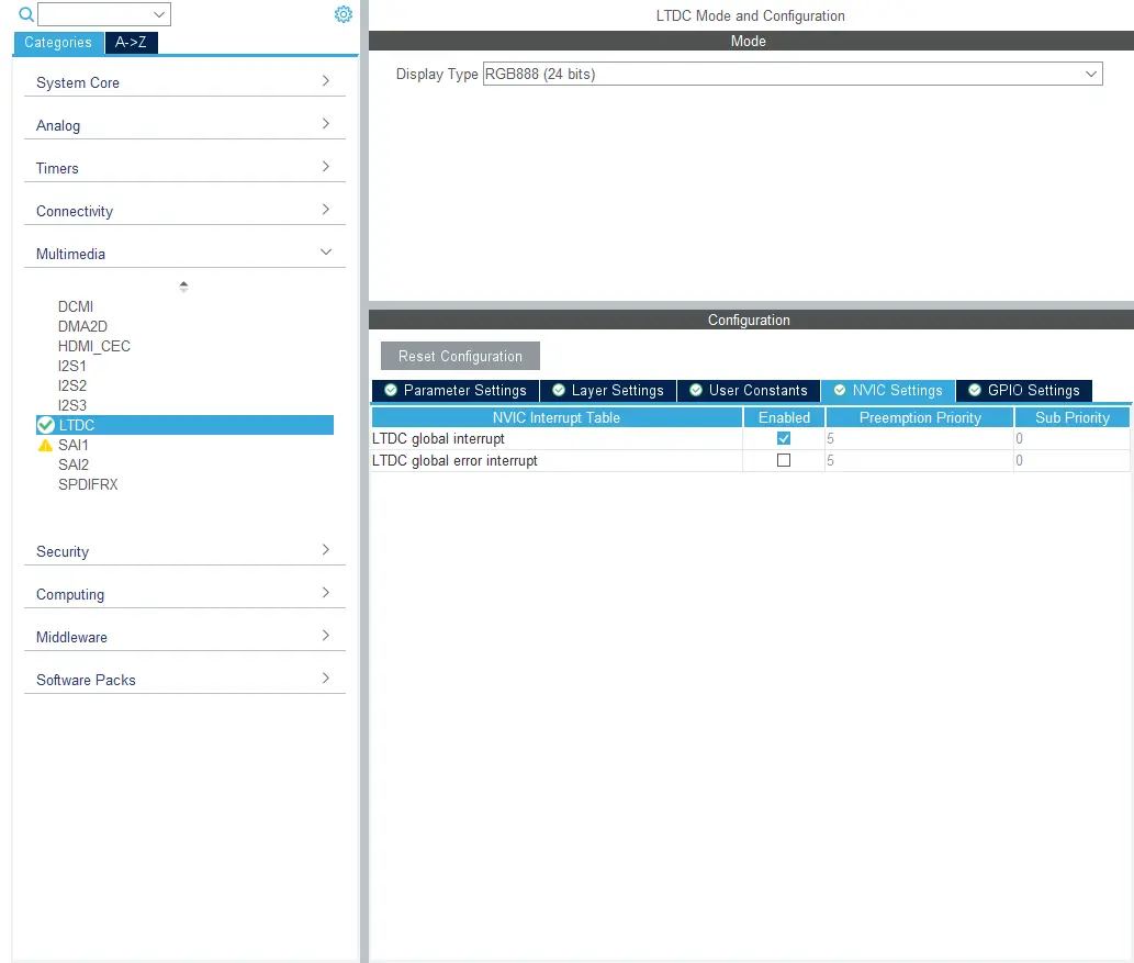
LTDC interrupt configuration
In addition to setting the checkmark in STM32CubeMX, the LTDC interrupts must all also manually be enabled in the code:
main.c
  /* USER CODE BEGIN LTDC_Init 2 */
  LTDC->IER |= LTDC_IER_LIE; // Enable LTDC interrupts
  /* USER CODE END LTDC_Init 2 */
In the interrupt handler you must reenable the interrupt after each time it fires.
stm32f7xx_it.c
void LTDC_IRQHandler(void)
{
  /* USER CODE BEGIN LTDC_IRQn 0 */
  /* USER CODE END LTDC_IRQn 0 */
  HAL_LTDC_IRQHandler(&hltdc);
  /* USER CODE BEGIN LTDC_IRQn 1 */
  HAL_LTDC_ProgramLineEvent(&hltdc,0);
  /* USER CODE END LTDC_IRQn 1 */
}
Check the Framerate
The LTDC interrupt will be used to drive the application forward. You should use a debugger to check that this interrupt is raised.
The time between these interrupts is the sum of clocking all the pixels and the porches. You can adjust the porches to adjust the framerate. The porches were part of the LTDC configuration. It is custom to lower the framerate by enhancing the vertical front porch.
An easy way to measure the framerate is to use the HAL_GetTick() in the interrupt handler:
stm32f7xx_it.c
volatile int last = 0;
volatile int diff = 0;
void LTDC_IRQHandler(void)
{
  /* USER CODE BEGIN LTDC_IRQn 0 */
  int now = HAL_GetTick();
  diff = now - last;
  last = now;
  /* USER CODE END LTDC_IRQn 0 */
  HAL_LTDC_IRQHandler(&hltdc);
  ...
Remember 60 frames per second should have 1000 ms / 60 = 16 ms between each frame.
SPI Display
We will now discuss a display connected with an SPI bus.
The configuration tasks for a display like this are:
- Configure the SPI peripheral and GPIOs
- Check the clocks
- Write or find the necessary driver code
SPI Configuration
Start in STM32CubeMX and enable the SPI. The images here are from an STM32G081 project:
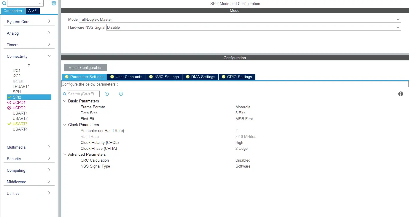
SPI configuration
Check the display datasheet for SPI format used (data size and bit order). Remember the 16 bit words are stored in little endian byte order in the framebuffer. Check if you can configure the display to accept this format. If not, then you have to convert data during transmission. Also pay attention to the clock polarity and clock phase. These are also specified in the display datasheet.
The SPI clock (the bit rate) is controlled by a divider to the FCLK. The minimum divider is 2. If the MCU is running e.g. 64 MHz, the maximum SPI bit rate will be 32 MBit/s.
On the GPIO tab you can check the GPIO selection for the SPI peripheral:
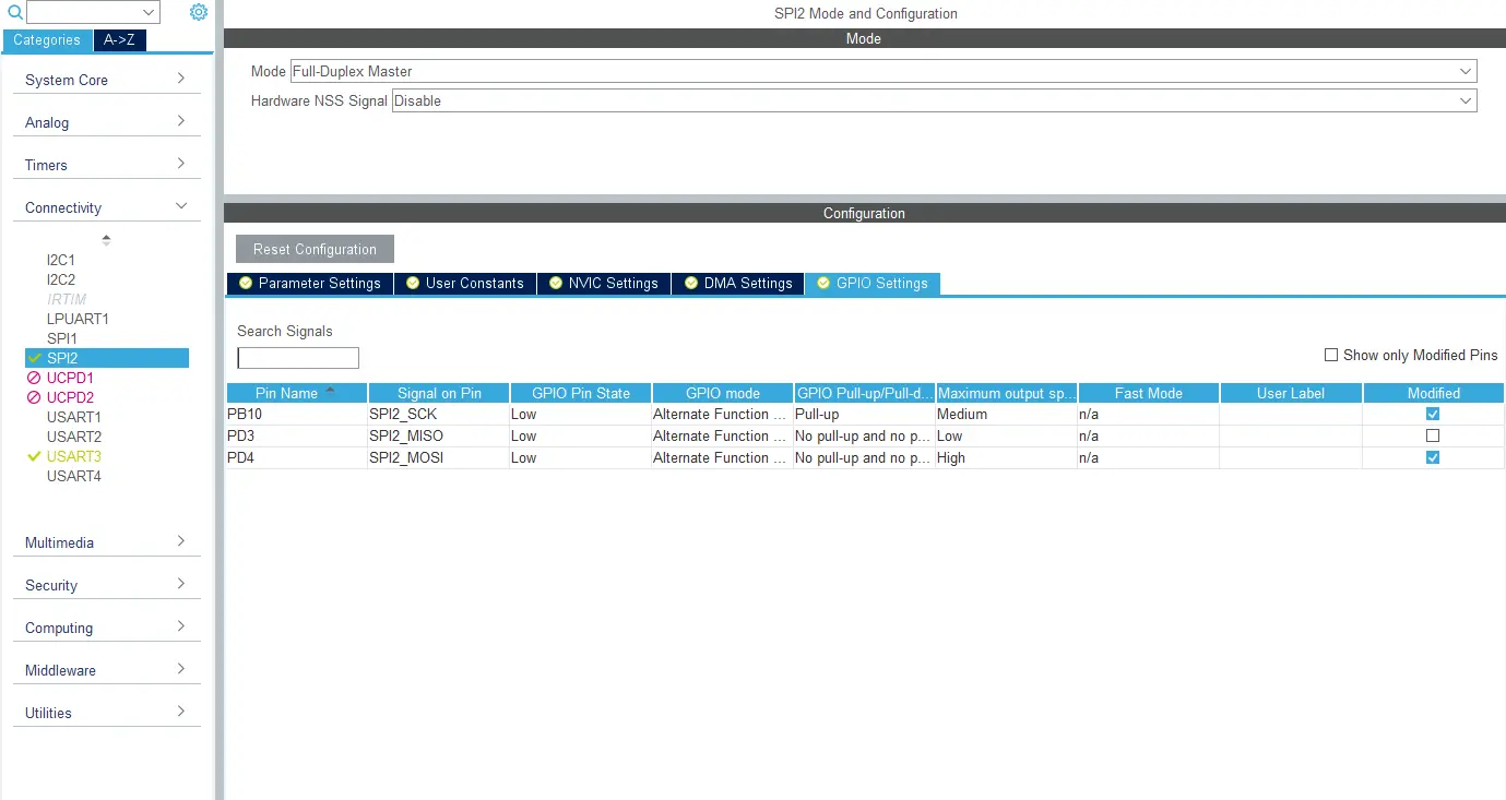
SPI GPIO configuration
Select the GPIOs on Pinout view on the right:
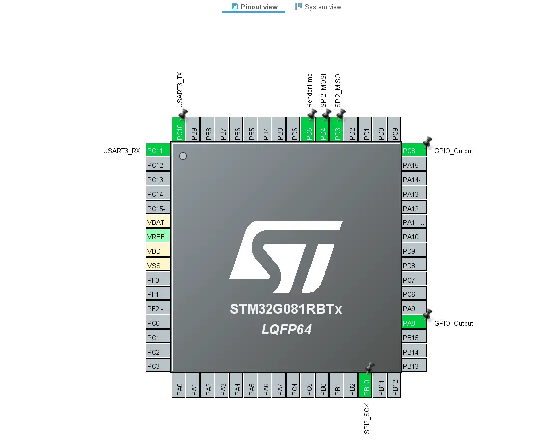
SPI GPIO selection
What is left now is to configure the display and transfer the framebuffer on the SPI channel. STM32CubeMX cannot generate this code for you, as it depends heavily on the display. For many displays it is necessary to send a sequence of commands and follow a specific power up sequence. After that you typically set the color mode and turn the display to ON. All this should be specified in the datasheet or examples provided by the vendor.
The STM32Cube Firmware contains examples using SPI communication. The STM32Cube HAL contains various helper functions. The basic function to send data is:
stm32g0xx_hal_spi.h
HAL_StatusTypeDef HAL_SPI_Transmit(SPI_HandleTypeDef *hspi, uint8_t *pData, uint16_t Size, uint32_t Timeout);
We recommend using these functions until communication is running stable. Afterwards performance can sometimes be improved by writing dedicated functions.
An SPI aware oscilloscope or SPI to usb logger can be very helpful in the process of writing a SPI display driver.
Note
Checking the Display Colors
At this point where you can transmit a framebuffer to the display, it is advisable to thoroughly check the display colors.
The idea is to write a color to the framebuffer and check the display by visual inspection. Here are a few examples:
| Test | Description |
|---|---|
| Red | Set red color in the framebuffer. The display must be red also. |
| Green | Set green color in the framebuffer. The display must be green also. |
| Blue | Set blue color in the framebuffer. The display must be blue also. |
| Dark color | A dark color (e.g. 0x8000) for 50% red, must be dark on the display. |
| Changing color | Change the framebuffer every second and see that the display also updates. |
To put a color in the RGB565 framebuffer, the following scheme can be used:
uint8_t r    = 0xff, g = 0x00, b = 0x00;             // Solid red
uint16_t col = ((r>>3)<<11) | ((g>>2)<<5) | (b>>3);  // Convert colors to RGB565
// Put colors into the framebuffer
for(int i = 0; i < W*H; i++)
{
  framebuffer[i] = col;
}
For a 24BPP display the code is better formulated using byte pointers (colors are stored in BGR order):
uint8_t framebuffer[480*272*3];  //24 bit framebuffer
...
uint8_t *fb = framebuffer;
while(fb < (uint8_t*)(framebuffer + (480*272*3)))
{
  *fb++ = 0x00; // Write blue color and increment pointer by one byte
  *fb++ = 0x00; // Write green color
  *fb++ = 0xFF; // Write red color
}
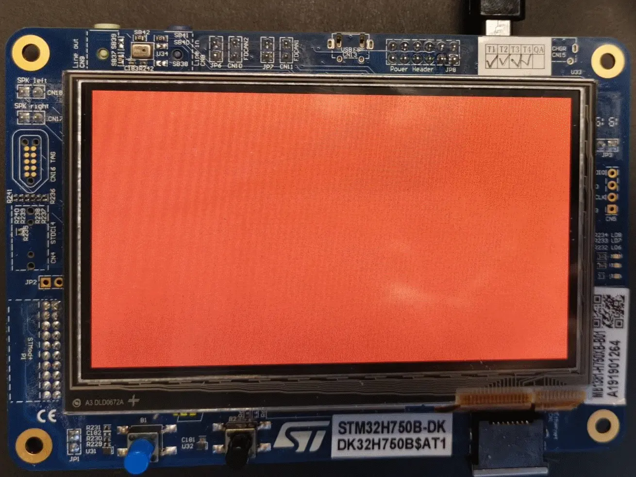
Showing a colored framebuffer
Changing the framebuffer every second by using the LTDC line event callback:
main.c
/* USER CODE BEGIN 4 */
uint8_t r = 0x00, g = 0x00, b = 0x00;
uint16_t col = 0;
uint8_t color = 1;
void HAL_LTDC_LineEventCallback(LTDC_HandleTypeDef* hltdc)
{
  static int count = 0;
  count++;
  if (count >= 60)
  {
    count = 0;
    switch (color)
    {
    case 1:
      r = 0xFF; g = 0x00; b = 0x00;
      color = 2;
      break;
    case 2:
      r = 0x00; g = 0xFF; b = 0x00;
      color = 3;
      break;
    case 3:
      r = 0x00; g = 0x00; b = 0xFF;
      color = 1;
      break;
    default:
      break;
    }
    col = ((r>>3)<<11) | ((g>>2)<<5) | (b>>3);  // Convert colors to RGB565
    // Put colors into the framebuffer
    for(int i = 0; i < W*H; i++)
    {
      framebuffer[i] = col;
    }
  }
}
/* USER CODE END 4 */