MJPEG Video
TouchGFX supports using MJPEG video starting from version 4.18. Video can be used to create more alive user interfaces or to show short instructions or user guides.
Video is included in the user interface through the Video Widget. This widget is available in the TouchGFX Designer and can be added to the user interface as any other widget.
Note
Extra support software is required to decode the video on a STM32
microcontroller. This software is easily included in the project by
enabling video support in the TouchGFX Generator. With a TouchGFX
Board Setup where video is enabled (see list below) it is easy to run
the video on the target by pressing Run Target (F6) as normal.
If you don't have video support in your target code, you will get compile or linker errors.
MJPEG video
MJPEG videos consists of a large number of JPEG images (frames) packed in a container file (.avi). The JPEG frames cannot be copied directly to the framebuffer as they are compressed. The individual frames must be decompressed into RGB format (16, 24 or 32 bit) before they can be shown on the display.
This decompression is computationally expensive and lowers the performance (i.e. frames per second) considerably compared to using RGB bitmaps.
The advantage of the JPEG compression is the much reduced size of the data.
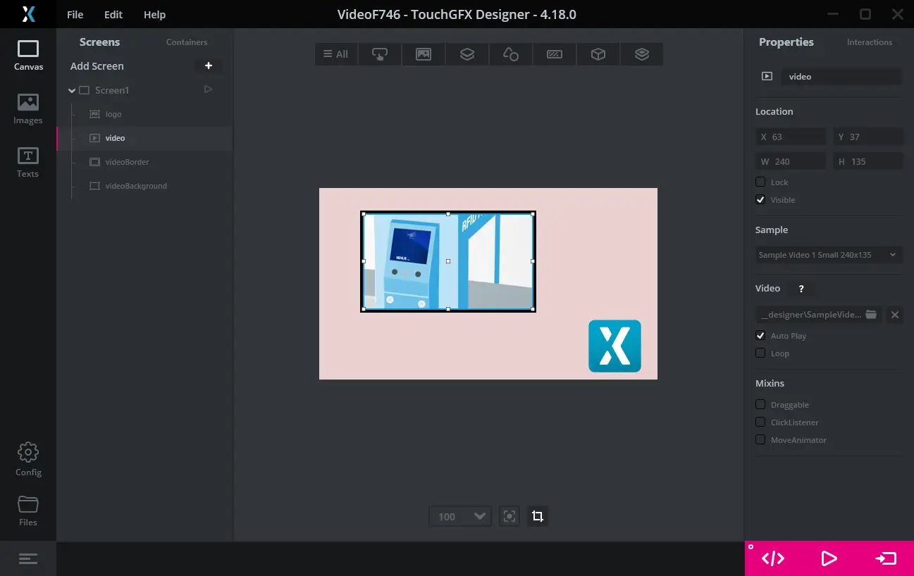
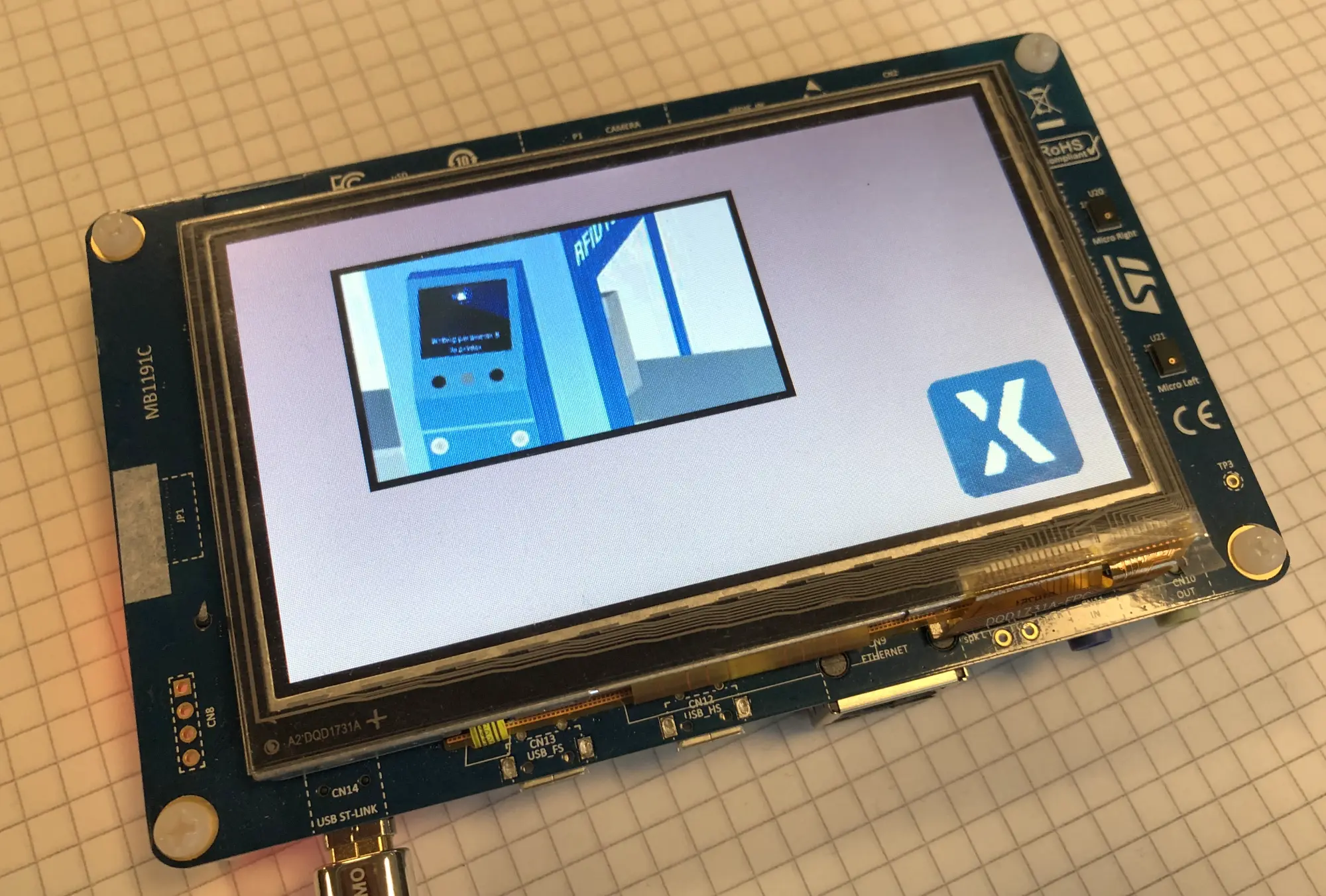
The video used in the above screenshots is 240 x 135 pixel. This means that each frame in 16-bit RGB format would take up 240 x 135 x 2 bytes = 64,800 bytes. The video contains 178 frames (approximately seven seconds). The total size of the video stored as bitmap would thus be 178 x 64,800 bytes = 11,534,400 bytes. The MJPEG AVI file is only 1,242,282 bytes or 10.7 % of the bitmaps.
This size reduction makes MJPEG video files very usefull for small sequences of video.
The reduced size comes with some compression artifacts (errors). These are often acceptable for real-world footage but can be unacceptable for high contrast graphics.
Some STM32 microcontrollers supports hardware accelerated decoding of JPEG images (e.g. STM32F769 or STM32H750). This speeds up the decoding of JPEG and increases the possible framerate of the video.
The decoding of a JPEG frame can easily take more than 16ms (depends on the MCU speed and the video resolution). This means that the decoding rate of a MJPEG video in most cases is lower than the normal frame rate of the user interface. For some applications it is acceptable to lower the overall frame rate to the decoding rate. For others it is required to keep the 60 fps frame rate of the user interface even if the video runs at e.g. 20 fps. An example is an application with an animated progress circle next to a video. The circle looks best if it is animated with 60 fps, even if the video only shows a new frame at 20 fps.
The above example on STM32F746 uses 18-20 ms for decoding the individual JPEG frames.
Using Video with TouchGFX
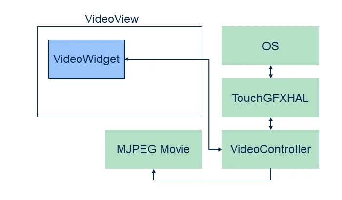
TouchGFX makes it easy to include a video as part of your user interface. You need three things: A Video widget, a VideoController, and of course your MJPEG video file.
The Video widget is used in your user interface as all other widgets. The video controller is part of the low level software that makes up a full TouchGFX environment (HAL, Operating System, drivers, etc.)
The VideoController consists of software that controls the decoding of the MJPEG file and buffer management.
The TouchGFX Designer automatically includes a video controller into
all simulator projects. This makes it very easy to use video in
simulator prototypes: Just add a Video widget, select a video file, and
press "Run Simulator" (F5).
To use video on hardware you also need a video controller in the target project (IAR, Keil, arm-gcc, CubeIDE). This is already added to some of the TouchGFX Board Specification packages (see list below), but you can add video support any project with the TouchGFX Generator. See the Generator User Guide.
When you have a video enabled platform it is easy to add and configure the Video widget in the Designer. The use of Video widget in the Designer is detailed here.
Video files in a TouchGFX project
When you include a video file in TouchGFX Designer it copies the .avi
file to the assets/vidoes folder. During code generation the video
is copied to generated/videos/bin as a .bin file and to
generated/videos/obj as a .o file. The .o and .bin contains the same
data, but the .o file is ELF format (which is preferred by some
compilers and IDE's).
The project updaters that are executed when generating code includes the video files in the target project. This means that the video files are linked into the executable and are available in the application.
The application programmer can add other videos to the assets/videos
folder. These will also be included in the project.
The file generated/videos/include/videos/VideoDatabase.hpp contains
symbolic information about the videos compiled into application:
const uint32_t video_SampleVideo1_240x135_bin_length = 1242282;
#ifdef SIMULATOR
extern const uint8_t* video_SampleVideo1_240x135_bin_start;
#else
extern const uint8_t video_SampleVideo1_240x135_bin_start[];
#endif
These declarations can be used to assign the video to a Video widget in user code.
Using video files from user code
In some projects it is not sufficient to select a video from within
the TouchGFX Designer. E.g. you want to select different videos at
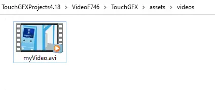
startup. First you must add the video file to assets/videos:
The video files in the assets/videos folder will be included in the
VideoDatabase.hpp when you generate code (or run make assets):
const uint32_t video_myVideo_bin_length = 1242282;
#ifdef SIMULATOR
extern const uint8_t* video_myVideo_bin_start;
#else
extern const uint8_t video_myVideo_bin_start[];
#endif
We can now use these declarations in user code to get the Video widget to play our movie:
Screen1View.cpp
#include <gui/screen1_screen/Screen1View.hpp>
#include <videos/VideoDatabase.hpp>

Screen1View::Screen1View()
{
}

void Screen1View::setupScreen()
{
    Screen1ViewBase::setupScreen();

    video.setVideoData(video_myVideo_bin_start, video_myVideo_bin_length);
    video.setWidthHeight(240, 136);
    video.play();
}
Note that the video data is now linked into the application. It is
possible to avoid this by not putting any videoes in assets/videos
and manually flash the video to a dedicated area in the external
flash. Then just pass the address and length using the flash address:
void Screen1View::setupScreen()
{
   ...
   video.setVideoData((const uint8_t*)0xA0200000, 1242282);
   ...
}
Limitations
TouchGFX does not support video decoding in portrait mode.
TouchGFX does not support audio. It is therefore recommended to remove audio data from the video data.
List of video enabled development kits
These development kits have video enabled by default in TouchGFX Board Setup package available in the TouchGFX Designer:
- STM32F769Discovery (hardware accelerated decoding)
- STM32H750BDiscovery (hardware accelerated decoding)
- STM32U5F9Discovery (hardware accelerated decoding)
- STM32F746Discovery (software based decoding)
If you are using another development kit or custom hardware, remember to enable video support in the TouchGFX Generator.
Creating MJPEG AVI files
Most videos are not stored in MJPEG AVI files as this is not a common video format anymore. It is therefore often necessary to convert a video file to MJPEG format before using it in a TouchGFX project.
Conversion can easily be done with for example FFMPEG. Other applications and online services are also available.
Using FFMPEG
Windows binaries for FFMPEG can be found here.
To convert the video file input.mov to MJPEG use this command:
ffmpeg -i input.mov -s 480x272 -vcodec mjpeg -q:v 1 -pix_fmt yuv420p -color_range 1 -strict -1 -an output.avi
The MJPEG video is in the output.avi file. This file can be copied to
the assets/videos.
To keep the correct aspect ratio of the video you can specify the width in pixels (here 480) and the height as '-1' (minus 1):
ffmpeg -i input.mov -vf scale=480:-1 -vcodec mjpeg -q:v 1 -pix_fmt yuv420p -color_range 1 -strict -1 -an output.avi
It is possible to cut out a section of a video using -ss to specify start time and -t or -to to specify duration or stop time:
ffmpeg -ss 3 -i input.mov -t 3 -s 480x272 -vcodec mjpeg -q:v 1 -pix_fmt yuv420p -color_range 1 -strict -1 -an output_section.avi
or:
ffmpeg -ss 3 -i input.mov -to 5 -s 480x272 -vcodec mjpeg -q:v 1 -pix_fmt yuv420p -color_range 1 -strict -1 -an output_section.avi
| Option | Description |
|---|---|
| -s | Output video resolution |
| -q:v | Video quality scale from 1..31 (from good to bad) |
| -an | Strip audio |
| -vf | Set filter graph |
| -ss | Start time in seconds |
| -t | Duration in seconds |
| -to | Stop time in seconds |
Note
[swscaler @ xxxxxxxxxxxxxxxx] deprecated pixel format used, make sure you did set range correctly
This is not important, shouldn't be taken into account.
Decoding Strategies
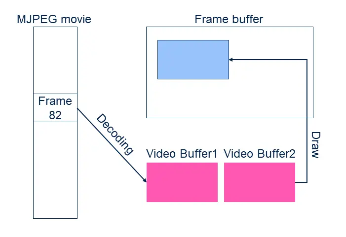
As mentioned above, TouchGFX needs to convert the individual MJPEG frames from JPEG to RGB before showing them on the framebuffer. This decoding can be done either on-the-fly when needed or asynchronous by decoding the next frame to a video buffer in advance.
The asynchronous decoding is done by second task, not the UI task. This means that the decoding in some cases can run in parallel with the UI task's drawing.
TouchGFX has 3 strategies, each with advantages and disadvantages:
| Strategy | Description |
|---|---|
| Direct To Frame Buffer | Decode the current video frame directly to the framebuffer when needed |
| Dedicated Buffer | Decode the next video frame to a video buffer. Copy from the video buffer to the frame buffer |
| Double Buffer | Decode the next video frame to a second video buffer. Swap video buffers when decoding is done |
The Designer always select the Direct To Frame Buffer strategy for simulator projects. The strategy used on target is configurable in the Generator.
The strategies are explained in detail below.
Direct To Frame Buffer
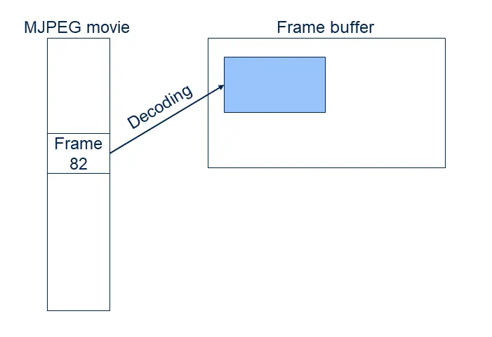
The Direct To Frame Buffer strategy decodes a JPEG frame during the rendering phase on the TouchGFX engine (see Rendering)
During the Update phase (see Update) the Video widget decides if the movie should be advanced to the next frame. During the following Rendering phase, the JPEG frame is decoded line-by-line to a "line buffer". The pixels are then converted to match the frame buffer format and copied to the framebuffer.
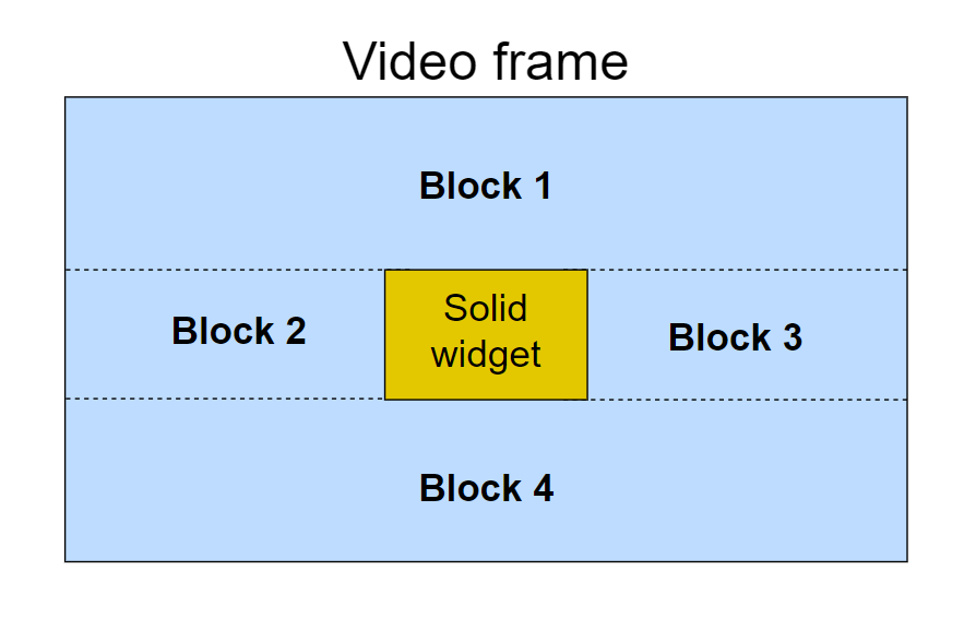
If the Video widget is covered by other solid widgets it is redrawn in multiple blocks (the visible parts are split into rectangles).
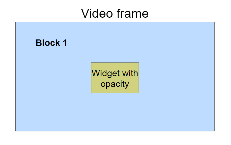
Drawing each of these blocks requires repeated decompression work. This can make this strategy unsuitable for user interface where other solid UI elements like Buttons are put on top of the video as the decoding time is increased. There are design decisions which can limit the amount of extra decompression work needed. One approach is to change the solid widget to have some amount of opacity. This will result in only one block, i.e., the whole video frame. The widget will be blended with the contents of the frame.Another approach is to disable the SMOC algorithm which partitions the areas
to draw in the screen into blocks. When disabled, all widgets are drawn
completely, even areas which are covered by other solid widgets. This is
done with useSMOCDrawing(). The example below disables SMOC for the screen
containing the video with solid widget(s) on top and enables it again when the
screen is done rendering.
void Screen1View::setupScreen()
{
    useSMOCDrawing(false);
    Screen1ViewBase::setupScreen();
}

void Screen1View::tearDownScreen()
{
    useSMOCDrawing(true);
    Screen1ViewBase::tearDownScreen();
}
The call to useSMOCDrawing() can also be placed closer to where the video
is rendered to avoid other widgets in the screen also being drawn completely.
The advantage of this solution is that only a little extra memory is used.
Caution
Dedicated Buffer
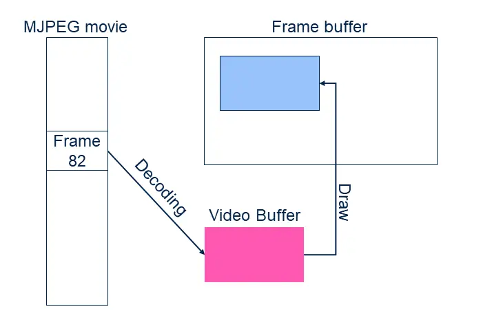
The Dedicated or single buffer decoding strategy decodes a JPEG frame to a dedicated RGB buffer first, and then later copies from that buffer to the frame buffer.
Opposed to the direct strategy the decoding now runs in a separate task, not the normal TouchGFX task. The Video widget calculates if a new movie frame should be shown in the next user interface tick and signals the decoding task to start decoding the next frame. During this decoding the video buffer cannot be drawn to the frame buffer (it is partly updated). The user interface is blocked from redrawing the video widget while the decoding is running. When the drawing is done, it will continue. If the user interface does not need to redraw the video, the user interface can continue as normal.
When the new video is fully decoded, the cost of rendering the video to the framebuffer is the same as drawing a bitmap (low). With this strategy it is therefore not a problem to put buttons or text on top of the video.
The disadvantage of this strategy the memory used by the task and the video buffer.
Double Buffer
The double buffered decoding strategy has two RGB buffers. The decoding is done into either of these buffers, whereas the rendering to the frame buffer happens from the other RGB buffer.
When a frame is decoded, the decoding task waits for the UI to show that video buffer and release the previous buffer. The decoding of the next frame can start as soon as the user interface has changed buffer.
An obvious disadvantage for this strategy is the memory usage which is doubled from the previous strategy.
Video frame rate and user interface frame rate
The decoding strategies has different effects on the user interface frame rate. The user interface frame rate is the number of (different) frames produced in the framebuffer per second.
With the direct to framebuffer strategy, the decoding speed of the video easily affects the effective frame rate of the user interface. Assume as an example that the decoding of one JPEG frame takes 28 ms, and that we want to show 20 video frames each second (20 fps). This is realistic as the total decoding time is: 28 ms x 20/s = 560 ms/s. The 20 fps corresponds to a new video frame in every third frame (of 60 fps). So in every third UI frame we want a new video frame, but as the decoding time is part of the rendering phase, the rendering of that frame takes 28 ms plus the rendering of the rest of the user interface, say 2 ms. The total rendering of the frame is 30 ms and we lost one tick, but are ready to produce a new frame for the next tick. In this next frame we are not decoding video, so here the rendering is below 16 ms and meets the limit. We can then start decoding the second video frame in the fourth tick.
The video frame rate is therefore 20 fps, and the user interface frame rate is 40 (out of 60 possible).
The result is that we cannot animate other elements of the UI with 60 fps because the video decoding limits the frame rate.
With the double buffer decoding strategy this is improved. The user interface always has a video buffer available with the latest frame. The decoder task can swap this buffer with the other buffer (containing the next frame) when it is available and the rendering thread is not actively drawing. After the swap the decoding task can immediately start decoding the next frame:
In UI frame 1 and 2 the UI is showing the first decoded video frame. Meanwhile the decoder is producing frame 2. In UI frame 3 this frame is ready and will be used. The decoder is free to start decoding the next frame (not shown in the figure).
It is thus possible to have user interface with other elements updated in every frame, even if the video decoding is only able to produce a new frame every 2 ticks.
Related articles
As mentioned above the video support for target project is configured in the TouchGFX Generator. See the Generator User Guide. for instructions.
The Video widget is available in the Designer. The use of Video widget in the Designer is detailed here.
