Canvas Widgets
Canvas Widgets and the Canvas Widget Renderer are a powerful and versatile add-on to TouchGFX which provides nice smooth, anti-aliased drawing of geometric shapes using relatively little memory while maintaining high performance. However, rendering geometrical shapes must be seen as a quite expensive operation and can easily strain the microcontrollers resources if not used carefully.
The Canvas Widget Renderer (hereafter referred to as CWR) is a general graphics API, providing optimized drawing for primitives, automatically eliminating most superfluous drawings. CWR is used by TouchGFX for drawing complex geometric shapes. Geometric shapes are defined by Canvas Widgets. TouchGFX comes with a number of supported Canvas Widgets but just like normal widgets you can make your own custom Canvas Widget to match your needs. Where a Canvas Widget defines the geometric shape of a figure to be drawn by the CWR, the actual color of each pixel inside the figure is defined by an associated Painter class. Again, TouchGFX comes with a number of Painters but you can make your own custom Painters to match your needs.
Using Canvas Widgets
Other widgets in TouchGFX have their sizes set automatically. A bitmap widget, for example, will automatically get the width and height of the contained bitmap. It is therefore enough to use setXY() on the bitmap widget to place the bitmap on the display.
Canvas Widgets do not have a default size which can be determined automatically and set initially. Care must be taken to not only position, but also size the widget correctly, otherwise the width and height of the Canvas Widget will be zero, and nothing will be drawn on the display.
So, instead of using setXY(), use setPosition() to place and size the canvas widget. See also Custom Canvas Widgets below for an example on how to create and use a custom canvas widget.
Once the position and size of the Canvas Widget has been set, a geometrical shape can be drawn inside it. The coordinate system will have (0, 0) in the upper left corner of the widget (not the display), the X axis stretches to the right and the Y axis stretches downwards.
Canvas widgets are also supported in TouchGFX Designer, and make the usage simple and has automatic memory requirement calculation and automatic memory allocation.
Available Canvas Widgets in the TouchGFX Designer:
Using these widgets via TouchGFX Designer, makes placement and size adjustment much easier by showing how the widget will look at run time.
Memory Allocation and Usage
To produce nice anti-aliased complex geometrical shapes additional memory is required. For this CWR has to have a special allocated memory buffer that is used during rendering. CWR, as the rest of TouchGFX, has no dynamic memory allocation.
Memory Allocation in TouchGFX Designer
When adding a widget to the canvas of a Screen, a memory buffer is automatically generated. The size of the buffer is based upon the width of the Screen with the following formula (Width × 3) × 5. This is however not always the ideal buffer size for all scenarios. Therefore the buffer size can be overridden has shown in the image below.
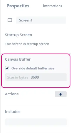
Canvas buffer size being overridden in Screen properties
Memory Allocation in User Code
The TouchGFX Designer only allocates a memory buffer for screens that
uses Canvas Widgets in the Designer. If you add Canvas Widgets in user
code in a screen that does not have Canvas Widgets in the Designer you
must manually setup a buffer. It is recommended to do this in the
Screen::setupScreen method.
Add this to your Screen class definition as private members:
private:
  static const uint16_t CANVAS_BUFFER_SIZE = 3600;
  static uint8_t canvasBuffer[CANVAS_BUFFER_SIZE]
Then in setupScreen() method of ScreenView.cpp the following line setting up the buffer can be added.
void ScreenView::setupScreen()
{
    ...
    CanvasWidgetRenderer::setupBuffer(canvasBuffer, CANVAS_BUFFER_SIZE);
    ...
}
The amount of CWR memory needed depends on the maximum size of the shapes that are to be drawn in the application. You can, however, reserve less memory than required by the most complex shape. To handle this situation, the CWR splits the drawing of shapes into smaller frame buffer parts resulting in slightly longer rendering time, as shapes in these cases will sometimes have to be rendered more than once. It is possible to investigate the memory consumption closer and fine-tune it when running in simulator mode. Simply add the following function call to your main.cpp:
CanvasWidgetRenderer::setWriteMemoryUsageReport(true);
Now whenever a draw operation finishes, CWR will report (print in the console) how much memory was required. For canvas_widget_example this could be “CWR requires 3604 bytes” (for the first draw operation) followed by “CWR requires 7932 bytes (4328 bytes missing)” (for the second draw operation). Even though it appears that CWR does not have enough memory (4328 bytes missing in this case) the application runs fine. This is because CWR detects that too little memory is available to complete the complex draw operation in a single run. Instead, it splits the draw operation into two separate draw operations and the shape will be drawn just fine but will require more time to render.
Setting the correct memory buffer size is therefore a trade off between memory and performance (rendering time). A good starting value is usually around 3000, but using the above technique, a better value can often be determined. If the shape is too complex and the allocated memory buffer is way too small, part of the shape will not be drawn (some vertical pixel lines will be skipped) and it is possible that nothing is drawn at all. In any case rendering time will increase a lot.
This means that if you want your application to render the CWR drawing at maximum speed you need to allocate the requested amount of memory. But if you can go with a slower rendering timer it is perfectly okay to reduce the memory buffer.
The CWR Coordinate System
The coordinate system in TouchGFX is normally used to address pixels for positioning bitmaps on the display. Bitmaps, texts and other graphic elements are all placed in a coordinate system, where (0,0) is the upper left hand pixel, the x-axis extends to the right and the y-axis extends downwards. In CWR it is not enough to be able to address pixels using integers, though this might be enough in special cases, this is far from enough in general. To demonstrate this, consider a circle with line width 1, which must fit precisely inside a box of 5 by 5 pixels. The center of this circle must be at (2.5, 2.5) and the radius must be 2 (the line is drawn .5 out from both sides of the circumference), so fractions are required for the center coordinate. Similarly, if the circle should fit inside a box of 6 by 6 pixels, the center must be at (3, 3) and the radius must be 2.5, so here fractions are required for the radius.
This new way of addressing coordinates for drawing graphics, means that the center of the pixel at (0,0) has CWR coordinate (0.5, 0.5). Hence, the box containing the pixel in the upper left corner of the screen has the following outline: (0,0) -> (1,0) -> (1,1) -> (0,1) -> (0,0).
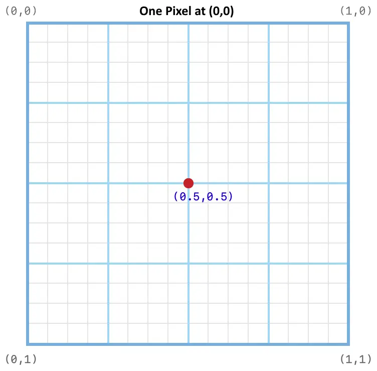
CWR coordinate system for pixel at (0,0)
Though this might seem confusing at first, it quickly becomes very natural. Where the coordinate system for bitmaps address the pixels, the same coordinate for Canvas Widgets address the gap just before and above the pixel.
Since circles are shapes that often will have to be moved half a pixel to place the center correctly, the function Circle::setPixelCenter() will place the circle center at the center of the given pixel, i.e. half a pixel further to the right and down, compared to the coordinates specified.
Custom Canvas Widgets
Implementing a custom Canvas Widget requires an implementation of a new class with the following functions:
virtual bool drawCanvasWidget(const Rect& invalidatedArea) const;
virtual Rect getMinimalRect() const;
The drawCanvasWidget() must draw whatever the custom widget needs to draw and getMinimalRect() should return the actual rectangle in the Widget which contains the geometrical shape.
Note
getMinimalRect() is that a geometrical shape can be moved around inside its widget and it is often impractical to resize and reposition the widget whenever the shape changes to only invalidate the smallest possible area. A dummy implementation of getMinimalRect() could simply return rect;, that is the size of the widget, but that would cause the entire area covered by the canvas widget to be redrawn, and not just the part of the canvas widget containing the geometrical shape. Very often, the geometrical shape occupies only a small part of the canvas widget.
Canvas Widgets all use the Canvas class, which encapsulates the Canvas Widget Renderer as described above. CWR has many optimizations applied automatically, though awareness of your geometrical shape in relation to the invalidated area, and avoiding unnecessary drawing outside the invalidated area, is always a good way to boost performance.
A rough implementation of a diamond shaped square inside a 10x10 box could look something like this:
#include <touchgfx/widgets/canvas/CanvasWidget.hpp>
#include <touchgfx/widgets/canvas/Canvas.hpp>

using namespace touchgfx;

class Diamond10x10 : public CanvasWidget
{
public:
  virtual Rect getMinimalRect() const
  {
    return Rect(0,0,10,10);
  }
  virtual bool drawCanvasWidget(const Rect& invalidatedArea) const
  {
    Canvas canvas(this, invalidatedArea);
    canvas.moveTo(5,0);
    canvas.lineTo(10,5);
    canvas.lineTo(5,10);
    canvas.lineTo(0,5);
    return canvas.render(); // Shape is automatically closed
  }
};
Note
getMinimalRect() returns to correct rectangle, or the graphics on screen might be wrong.In order to see the Diamond10x10 on the display, the color must be set up by passing a Painter to the diamond. Read more about Painters in the next section. Also, the Diamond10x10 must be placed and sized correctly. This could look similar to this:
In the header file declare
Diamond10x10 box;
PainterRGB565 myPainter; // For 16bpp displays
and in the code you should have something like this in setupScreen():
myPainter.setColor(Color::getColorFromRGB(0xFF, 0x0, 0x0));
box.setPosition(100,100,10,10);
box.setPainter(myPainter);
add(box);
Painters
A Painter defines a coloring scheme to fill a Canvas Widget object, thus painters are needed to make shapes visible. A painter can supply a single color for all pixels, e.g. PainterRGB565, or copy each pixel from a supplied bitmap, e.g. PainterRGB565Bitmap. Since a painter writes the pixels directly to the framebuffer, the selected painter must match the format of the framebuffer or dynamic bitmap. TouchGFX comes with painters for all supported displays with painters specific for a solid color, or drawing a bitmap.
Painter classes
The following table lists the available painters in TouchGFX. When you use Canvas Widgets with the TouchGFX Designer, the Designer will select the correct painter, but if you write code yourself that uses Canvas Widgets, you must select a suitable painter.
| Framebuffer format | Color Painter | Bitmap painters |
|---|---|---|
| BW | PainterBW | PainterBWBitmap |
| GRAY2 | PainterGRAY2 | PainterGRAY2Bitmap |
| GRAY4 | PainterGRAY4 | PainterGRAY4Bitmap |
| ABGR2222 | PainterABGR2222 | PainterABGR2222Bitmap |
| ARGB2222 | PainterARGB2222 | PainterARGB2222Bitmap |
| BGRA2222 | PainterBGRA2222 | PainterBGRA2222Bitmap |
| RGBA2222 | PainterRGBA2222 | PainterRGBA2222Bitmap |
| RGB565 | PainterRGB565 | PainterRGB565Bitmap, PainterRGB565L8Bitmap |
| RGB888 | PainterRGB888 | PainterRGB888Bitmap, PainterRGB888L8Bitmap |
| ARGB8888 | PainterARGB8888 | PainterARGB8888Bitmap, PainterARGB8888L8Bitmap |
| XRGB8888 | PainterXRGB8888 | PainterXRGB8888Bitmap, PainterXRGB8888L8Bitmap |
The bitmap painters support various bitmap formats:
| Painter | Supported bitmap formats |
|---|---|
| PainterBWBitmap | BW, BW_RLE |
| PainterGRAY2Bitmap | GRAY2 |
| PainterGRAY4Bitmap | GRAY4 |
| PainterABGR2222Bitmap | ABGR2222 |
| PainterARGB2222Bitmap | ARGB2222 |
| PainterBGRA2222Bitmap | BGRA2222 |
| PainterRGBA2222Bitmap | RGBA2222 |
| PainterRGB565Bitmap | RGB565, ARGB8888 |
| PainterRGB565L8Bitmap | L8_RGB565, L8_RGB888, L8_ARGB8888 |
| PainterRGB888Bitmap | RGB888, ARGB8888 |
| PainterRGB888L8Bitmap | L8_RGB565, L8_RGB888, L8_ARGB8888 |
| PainterARGB8888Bitmap | RGB565, RGB888, ARGB8888 |
| PainterARGB8888L8Bitmap | L8_RGB565, L8_RGB888, L8_ARGB8888 |
| PainterXRGB8888Bitmap | RGB565 (no transparency), RGB888, ARGB8888 |
| PainterXRGB8888L8Bitmap | L8_RGB565, L8_RGB888, L8_ARGB8888 |
Tiled bitmaps
Painters that draw pixels from a bitmap puts the bitmap in upper left corner of the Canvas Widget. The pixels of the shape that are outside of the bitmap dimension is not drawn.
The bitmap painters can be configured to repeat the widget (tiled) to cover the whole shape.
Tiling is enabled by calling the setTiled(bool) method on your painter:
    PainterRGB888Bitmap bitmapPainter;
    ...
    bitmapPainter.setBitmap(touchgfx::Bitmap(BITMAP_BLUE_LOGO_TOUCHGFX_LOGO_ID));
    bitmapPainter.setTiled(true);
Tiling can not be enabled in the Designer.
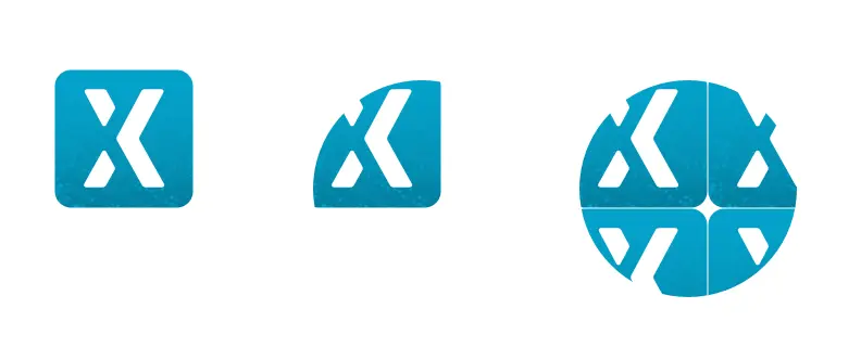
An application showing an Image, Circle with bitmap painter, and Circle with tiling bitmap painter.
Custom Painters
Even though TouchGFX comes with a set of predefined painter classes covering most use case scenarios, custom painters can also be implemented.
In this section we will give a few examples, that can be used as inspiration. The examples are for 16bpp RGB565 only. Slight modifications must be done for other framebuffer formats.
A custom painter is just a subclass of the AbstractPainter class. Painters for 16bpp (RGB565) framebuffers can use the AbstractPainterRGB565 class as superclass. Painters for 24bpp (RGB888) framebuffers can use AbstractPainterRGB888 as superclass.
These super classes are abstract classes. The custom painter class must implement the method:
virtual void paint(uint8_t* destination, int16_t offset, int16_t widgetX, int16_t widgetY, int16_t count, uint8_t alpha) const = 0;
The destination points to the start position in the framebuffer (the
left edge of the widget).
The offset is how many pixels from this start position to put the first pixel.
widgetX, widgetY are the coordinates of the first pixel relative to widget (given in the framebuffer coordinate system).
count is the number of pixels to draw with the specified alpha.
The Canvas Widgets will call this method many times, so it is very important that the implementation of paint is not slow. If the Canvas Widget is not updated often, this is less important.
Color painters
The simplest painter just writes a fixed color to the framebuffer. Here is how to implement that:
#include <touchgfx/widgets/canvas/AbstractPainterRGB565.hpp>
using namespace touchgfx;
class RedPainter : public AbstractPainterRGB565
{
public:
    virtual void paint(uint8_t* destination, int16_t offset, int16_t widgetX, int16_t widgetY, int16_t count, uint8_t alpha) const
    {
        uint16_t* framebuffer = reinterpret_cast<uint16_t*>(destination) + offset; // Address of first pixel to paint
        const uint16_t* const lineend = framebuffer + count; // Address of last pixel to paint
        const uint16_t redColor565 = 0xF800;  // Full red in RGB565
        do
        {
            *framebuffer = redColor565;
        } while (++framebuffer < lineend);
    }
};
Remember to create an instance of your painter and assign it to your Canvas widget. Add a member of the painter type to your class:
Circle myCircle;
RedPainter myPainter;
and in the code you should have something like this in setupScreen():
...
myCircle.setPainter(myPainter);
...
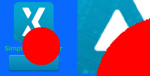
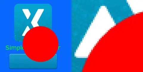
The RedPainter painting a Circle. On the right a magnified part.
The RedPainter class above ignores the alpha parameter. This makes the edges harsh (no alpha-blending) as all pixels are made fully red. We can improve this with a slight code update where we use the alpha parameter to do blending if needed:
#include <touchgfx/widgets/canvas/AbstractPainterRGB565.hpp>
using namespace touchgfx;
class AlphaRedPainter : public AbstractPainterRGB565
{
public:
    virtual void paint(uint8_t* destination, int16_t offset, int16_t widgetX, int16_t widgetY, int16_t count, uint8_t alpha) const
    {
        uint16_t* framebuffer = reinterpret_cast<uint16_t*>(destination) + offset; // Address of first pixel to paint
        const uint16_t* const lineend = framebuffer + count;
        const uint16_t redColor565 = 0xF800;  // Full red in RGB565
        do
        {
            if (alpha == 0xFF)
            {
                *framebuffer = redColor565; // Write red to framebuffer
            }
            else
            {
                *framebuffer = alphaBlend(redColor565, *framebuffer, alpha); // Blend red with the framebuffer color
            }
        } while (++framebuffer < lineend);
    }
};
The function alphaBlend blends two RGB565 pixels with a given alpha for the first pixel. The function is provided by the super class AbstractPainterRGB565. The circle now has smooth edges with this code:
The RedAlphaPainter painting a Circle. On the right a magnified part showing alpha blending.
The WidgetX and WidgetY parameters can be used to restrict the drawing to certain areas. Here is for example a painter that only draws on every other horizontal line. The WidgetY is used to control that:
#include <touchgfx/widgets/canvas/AbstractPainterRGB565.hpp>
using namespace touchgfx;
class StripePainter : public AbstractPainterRGB565
{
public:
    virtual void paint(uint8_t* destination, int16_t offset, int16_t widgetX, int16_t widgetY, int16_t count, uint8_t alpha) const
    {
        if ((widgetY & 2) == 0)
        {
            return; // Do not draw anything on line 0,1, 4,5, 8,9, etc.
        }
        uint16_t* framebuffer = reinterpret_cast<uint16_t*>(destination) + offset;
        const uint16_t* const lineend = framebuffer + count;
        if (alpha == 0xFF)
        {
            do
            {
                *framebuffer = 0xF800;
            } while (++framebuffer < lineend);
        }
        else
        {
            do
            {
                *framebuffer = alphaBlend(0xF800, *framebuffer, alpha);
            } while (++framebuffer < lineend);
        }
    }
};
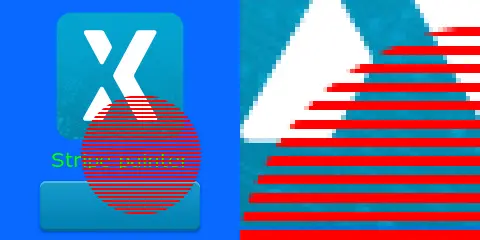
The StripePainter painting a Circle. On the right a magnified part.
Changing the framebuffer
The painter in this section does not paint a specific content to the framebuffer, but changes the framebuffer to be gray-scale. It does this by reading the pixel value in the framebuffer (written by the Widgets that are in the background of the Circle), extracting the green component, using this to create a gray color (same value for red, green, blue), and writing that back to the framebuffer.
Many similar techniques can be developed using this principle of reading and modifying the framebuffer.
#include <touchgfx/widgets/canvas/AbstractPainterRGB565.hpp>
#include <touchgfx/Color.hpp>
using namespace touchgfx;
class GrayscalePainter : public AbstractPainterRGB565
{
public:
    virtual void paint(uint8_t* destination, int16_t offset, int16_t widgetX, int16_t widgetY, int16_t count, uint8_t alpha) const
    {
        uint16_t* framebuffer = reinterpret_cast<uint16_t*>(destination) + offset;
        const uint16_t* const lineend = framebuffer + count;
        do
        {
            const uint8_t green = Color::getGreenFromRGB565(*framebuffer) & 0xF8; // Keep only 5 bits of the green
            const uint16_t color565 = LCD16bpp::getNativeColorFromRGB(green, green, green);
            if (alpha == 0xFF)
            {
                *framebuffer = color565;
            }
            else
            {
                *framebuffer = alphaBlend(color565, *framebuffer, alpha);
            }
        } while (++framebuffer < lineend);
    }
};
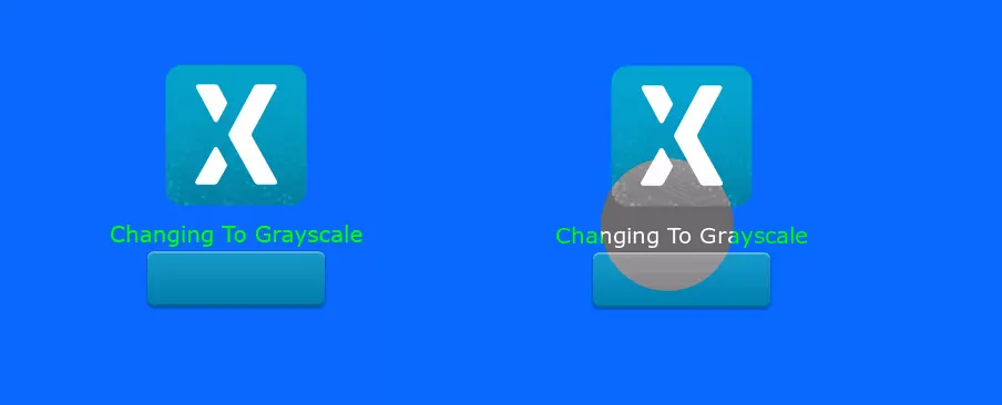
Original background on the left. On the right the Circle painter has changed the inner pixels in the circle to gray-scale.
Custom Containers on rotated displays
If your application is using a rotated display, the custom container code must take this into account, if it is using the coordinates in the painting.
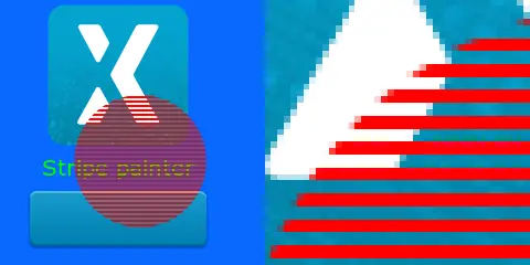
Here is the StripePainter used with a rotated display:
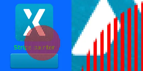
The StripePainter painting a Circle. On the right a magnified part.
The Image, text, and the Button has been rotated by the TouchGFX
engine, but we see that the stripes are now perpendicular to the text,
where it is supposed to parallel. The lines have not been rotated.
The problem is that the framebuffer is not rotated, so as the painter
paints in sequential addresses (pixels in the framebuffer), the lines
are oriented as before (not rotated).
We can fix that by using the WidgetX to decide if we are painting or not. The widgetX and widgetY parameters are given in the framebuffer coordinate system. This means that widgetX grows when we go down on the display and corresponds to y in the display coordinate system.
#include <touchgfx/widgets/canvas/AbstractPainterRGB565.hpp>
#include <touchgfx/Color.hpp>
using namespace touchgfx;
class StripePainterRotate90 : public AbstractPainterRGB565
{
public:
    virtual void paint(uint8_t* destination, int16_t offset, int16_t widgetX, int16_t widgetY, int16_t count, uint8_t alpha) const
    {
        uint16_t* framebuffer = reinterpret_cast<uint16_t*>(destination) + offset;
        const uint16_t* const lineend = framebuffer + count;
        if (alpha == 0xFF)
        {
            do
            {
                if (widgetX++ & 2)
                {
                    *framebuffer = 0xF800;
                }
            } while (++framebuffer < lineend);
        }
        else
        {
            do
            {
                if (widgetX++ & 2)
                {
                    *framebuffer = alphaBlend(0xF800, *framebuffer, alpha);
                }
            } while (++framebuffer < lineend);
        }
    }
};
The stripes are now correctly oriented:
The StripePainterRotate90 painting a Circle.