자습서 7: TSD 노브 디스플레이용 애플리케이션 생성
이 자습서에서는 TSD TSS013004A-AD 디스플레이 노브 모듈용 애플리케이션을 생성하고 로드하는 방법을 다룹니다. 이 제품은 STM32C091 + 8MB 외부 플래시를 기반으로 한 그래픽 엔트리 레벨 1.3인치 원형 디스플레이 모듈로, 부분 프레임 버퍼를 실행합니다. 이 애플리케이션은 간단한 GUI를 제공하며 디스플레이 모듈의 인터페이스(물리적 제어 장치, 주변 광도, UART 통신) 사용 방법을 보여줍니다. TSD TSS013004A-AD 디스플레이 노브 모듈의 MCU 플랫폼은 다음과 같은 사양을 갖습니다.
- 48MHz CPU(STM32C091)
- 36kB 내부 SRAM
- 256kB 내부 플래시
- 8MB 외부 시리얼 플래시
- 24MHz SPI 디스플레이 인터페이스
이 자습서를 따라하려면 자습서 1 및 자습서 2를 먼저 완료하는 것이 좋습니다.
1단계: TouchGFX 프로젝트 시작하기
TouchGFX Designer에서는 디스플레이 모듈용 애플리케이션 템플릿(TBS)이 제공되며, 이는 모든 기본 기능을 설정합니다. 다음을 기반으로 새 프로젝트 생성:
- "Create" 탭에서 "TSDHD TSS013-1"이라는 보드를 선택하십시오.
- "Application Name"을 예를 들어 "KnobApplication"으로 설정하십시오.
- "Create"를 클릭합니다.
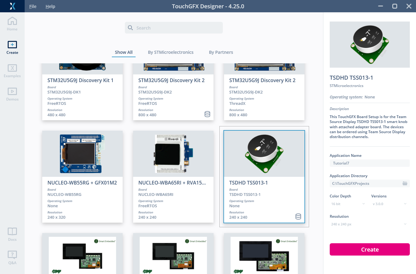
디스플레이 모듈용 프로젝트 생성
2단계: 기본 GUI 구축하기
프로젝트를 생성한 후, 240 x 240 픽셀 크기의 빈 캔버스가 생성됩니다. 이 단계에서는 애플리케이션의 GUI를 설계할 것입니다. 단일 화면(Screen1)이 다음과 같이 표시됩니다.
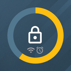
이 자습서에서 구축한 GUI의 스크린샷
이 항목의 이미지 애셋은 이 링크에서 다운로드할 수 있습니다. 파일을 프로젝트의 TouchGFX/assets/images 폴더에 압축 해제합니다. GUI를 생성하려면 이 표에 따라 TouchGFX Designer에서 위젯을 추가하고 구성하십시오.
| 순서 | 위젯 | 이름 | 속성 |
|---|---|---|---|
| 1 | 이미지 | backgroundImage |
|
| 2 | CircleProgress | valueCircleProgress |
|
| 3 | 이미지 | wifiImage |
|
| 4 | 이미지 | alarmImage |
|
| 5 | 이미지 | unlockedImage |
|
| 6 | 이미지 | lockedImage |
|
3단계: 애플리케이션을 디스플레이에 프로그래밍하기
이제 디스플레이에서 GUI를 확인하기 위해 디스플레이 모듈에 예비 애플리케이션을 프로그래밍합니다. STMicroelectronics에서 제작한 모든 디스커버리 키트 및 NUCLEO 보드에는 ST-LINK 하드웨어가 탑재되어 있으며, 이는 일반적으로 해당 보드에 애플리케이션을 프로그래밍하는 데 사용됩니다. 이 타사 디스플레이 모듈에는 내장형 ST-LINK가 없습니다. 대신, 다음 두 가지 대체 방법을 사용하여 프로그래밍할 수 있습니다.
UART를 이용한 프로그래밍
디스플레이 모듈 어댑터 보드에는 USB-UART 변환 칩이 탑재되어 있어, PC와 디스플레이 모듈 내부의 MCU 간 통신을 활성화합니다. 또한 MCU 부트로더의 UART 인터페이스를 활용하여 디스플레이 모듈을 이 방식으로 프로그래밍할 수도 있습니다. 이는 TouchGFX Designer의 “Run target”을 클릭할 때 이 프로젝트의 Makefile에서 사용되는 방법입니다. 이 프로젝트의 “Run target” 스크립트가 작동하려면 다음 요구 사항이 필요합니다.
- 디스플레이 모듈은 데이터 USB 케이블을 통해 PC에 연결됩니다.
- STM32CubeProgrammer(v2.18.0 이상)는 기본 위치에 설치됩니다.
- USB-UART 드라이버가 설치되었습니다. 여기(https://www.wch-ic.com/downloads/ch341ser_exe.html)에서 다운로드 가능합니다.
- MCU의 nBOOT_SEL 옵션 바이트는 FALSE로 설정되어야 합니다. 이는 제공된 모듈의 기본값입니다.
“Run target”을 클릭하고 컴파일 및 프로그래밍이 완료될 때까지 기다린 후, Designer 캔버스의 GUI가 모듈 디스플레이에 표시되어야 합니다.
Tip
Further reading
- MCU의 RESET 및 BOOT0 핀에 신호를 인가하여 MCU를 내장 부트로더로 재부팅하십시오.
- ST OpenBootloader 기반의 커스텀 부트로더를 MCU RAM에 프로그래밍하고 실행하여 외부 플래시를 프로그래밍할 수 있도록 합니다.
- MCU의 내장 플래시와 외부 플래시에 TouchGFX 애플리케이션을 프로그래밍하십시오.
- MCU의 RESET 핀을 펄싱하여 MCU를 TouchGFX 애플리케이션으로 재부팅합니다.
외부 ST-LINK를 사용한 프로그래밍
모듈을 프로그래밍하는 또 다른 방법은 디스플레이 모듈 어댑터 보드의 핀에 와이어를 연결하여 외부 디버거를 사용하는 것입니다. ST-LINK/V2 디버거를 사용할 때는 아래 표와 같이 와이어 연결이 필요합니다.
| ST-LINK/V2, 20핀 커넥터 | 노브 어댑터 보드 |
|---|---|
| 1 | 5V |
| 4 | GND |
| 7 | SWD |
| 9 | SWC |
ST-LINK 및 STM32CubeProgrammer를 사용해 외부 플래시도 로드할 수 있도록, 프로젝트의 Loading/TSDHD-TSS013-1.stldr에 외부 로더 파일이 제공됩니다. ST-LINK를 사용하는 한 가지 장점은 프로그래밍뿐만 아니라 STM32CubeIDE 등을 통해 실행 중인 애플리케이션을 디버깅할 수 있다는 점입니다.
이 자습서를 따라하는 데는 외부 ST-LINK가 필요하지 않습니다.
4단계: 물리적 입력에 상호작용(Interaction) 추가하기
디스플레이 노브 모듈에는 왼쪽으로 돌리기, 오른쪽으로 돌리기, 누르기에 해당하는 세 가지 물리적 사용자 입력 방식이 있습니다. 이 단계에서는 노브를 돌릴 때 GUI가 CircleProgress의 값을 변경하고, 노브를 누를 때 화면 잠금을 켜거나 끄도록 설정합니다.
TouchGFX/target/KeySampler.cpp 내의 코드는 하드웨어 입력을 읽고 이를 서로 다른 키 ID에 매핑합니다. 이러한 버튼은 아래와 같이 TouchGFX Designer에서 “하드웨어 버튼” 상호작용을 트리거하는 데 사용할 수 있습니다.
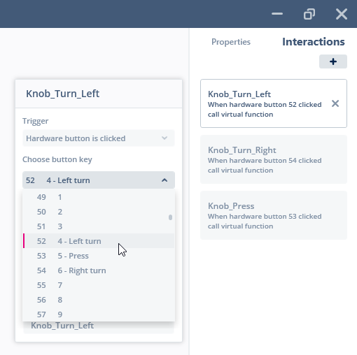
ToucHGFX Designer에서 하드웨어 버튼을 입력으로 사용하는 방법
아래 표에 따라 입력값마다 하나의 상호작용을 추가하십시오.
| 상호작용 | 속성 |
|---|---|
| Knob_Turn_Left |
|
| Knob_Turn_Right |
|
| Knob_Press |
|
TouchGFX Designer에서 상호작용을 추가하고 코드를 생성한 후, 지정된 가상 함수를 호출하는 코드가 이제 TouchGFX/generated/gui_generated/src/screen1_screen/Screen1ViewBase.cpp에 생성됩니다. 따라서 원하는 기능을 구현하려면 사용자 코드 화면 클래스 헤더 파일에 해당 함수들(및 헬퍼 함수)을 추가해야 합니다.
TouchGFX/gui/include/gui/screen1_screen/Screen1View.hpp
public:
...
    virtual void toggleLock();
    virtual void decrementValue();
    virtual void incrementValue();
    void changeValue(int change);
그리고 사용자 코드 화면 클래스 소스 파일에 이를 구현합니다.
TouchGFX/gui/src/screen1_screen/Screen1View.cpp
void Screen1View::toggleLock()
{
    lockedImage.setVisible(!lockedImage.isVisible());
    lockedImage.invalidate();
}

void Screen1View::decrementValue()
{
    if (!lockedImage.isVisible())
    {
        changeValue(-5);
    }
}

void Screen1View::incrementValue()
{
    if (!lockedImage.isVisible())
    {
        changeValue(5);
    }
}

void Screen1View::changeValue(int change)
{
    const int newValue = valueCircleProgress.getValue() + change;
    valueCircleProgress.updateValue(newValue, 0);
}
디스플레이 모듈은 이제 업데이트된 애플리케이션으로 프로그래밍할 수 있습니다. 이제 노브를 눌러 GUI 잠금을 해제한 후, 노브를 돌려 CircleProgress 값을 변경할 수 있습니다.
Tip
5단계: LED 주변 조명 제어하기
디스플레이 노브 모듈에는 주변 조명을 위해 켜질 수 있는 빨간색, 초록색, 파란색 LED 링이 장착되어 있습니다. 각 색상 채널은 MCU의 PWM 지원 출력으로 제어됩니다. 사용 중인 애플리케이션 템플릿에서 이 조명을 제어하는 함수는 Core/Inc/knob_interface.cpp에 구현되고 Core/Src/knob_interface.hpp를 통해 사용할 수 있습니다.
Core/Src/knob_interface.hpp
public:
...
void knobSetAmbientLightRGB(uint8_t red, uint8_t green, uint8_t blue);
...
이 데모에서는 CircleProgress의 값에 따라 빛의 색상을 제어할 것입니다. 이를 구현하여 값이 0일 때는 빛이 파란색이며, 값이 증가함에 따라 보라색을 거쳐 점진적으로 빨간색으로 전환되도록 합니다. 이는 다음 코드를 Screen1View에 추가하면 됩니다.
TouchGFX/gui/src/screen1_screen/Screen1View.cpp
#include <gui/screen1_screen/Screen1View.hpp>
#ifndef SIMULATOR
#include "knob_interface.hpp"
#endif

void Screen1View::setupScreen()
{
    Screen1ViewBase::setupScreen();
    changeValue(0); // Ensure that the system state is synchronized at start-up
}

void Screen1View::changeValue(int change)
{
    const int newValue = valueCircleProgress.getValue() + change;
    valueCircleProgress.updateValue(newValue, 0);

#ifndef SIMULATOR
    const int value = valueCircleProgress.getValue(); // Always inside the range set in TouchGFX Designer (0-100)

    //Update ambient light
    const uint8_t red = (value * 255) / 100;
    const uint8_t green = 0;
    const uint8_t blue = 255 - red;
    knobSetAmbientLightRGB(red, green, blue);
#endif
}
디스플레이 모듈에서 애플리케이션을 실행하면, 노브가 잠금 해제되어 회전될 때 주변 조명이 활성화되고 색상이 변경됩니다.
Tip
6단계: UART로 데이터 전송하기
노브 디스플레이 모듈은 UART 통신 인터페이스와 커넥터 케이블을 통해 외부에서 사용할 수 있는 6개의 GPIO(PA0-5)를 갖추고 있습니다. 이 단계에서는 CircleProgress 값이 업데이트될 때마다 애플리케이션이 UART를 통해 ASCII 문자열을 전송하도록 합니다. UART 인터페이스는 디스플레이 모듈용 템플릿 프로젝트에서 구성되며 Core/Src/knob_interface.hpp를 통해 사용할 수 있습니다.
Core/Src/knob_interface.hpp
public:
...
void knobUartSendByte(uint8_t data);
void knobUartSendBytes(uint8_t* data, uint16_t size);
void knobUartSendString(uint8_t* data);
...
여기서는 값을 나타내는 문자열의 서로 다른 ASCII 문자를 전송하기 위해 knobUartSendByte 함수를 여러 번 사용합니다.
TouchGFX/gui/src/screen1_screen/Screen1View.cpp
void Screen1View::changeValue(int change)
{
    const int newValue = valueCircleProgress.getValue() + change;
    valueCircleProgress.updateValue(newValue, 0);

#ifndef SIMULATOR
    const int value = valueCircleProgress.getValue(); // Always inside the range set in TouchGFX Designer (0-100)

    //Update ambient light
    const uint8_t red = (value * 255) / 100;
    const uint8_t green = 0;
    const uint8_t blue = 255 - red;
    knobSetAmbientLightRGB(red, green, blue);

    // Send new value on UART
    knobUartSendByte('0' + value / 100);
    knobUartSendByte('0' + (value % 100) / 10);
    knobUartSendByte('0' + value % 10);
    knobUartSendByte('\r');
    knobUartSendByte('\n');
#endif
}
디스플레이 모듈에서 애플리케이션을 실행할 때, 노브가 잠금 해제된 상태에서 회전하면 UART를 통해 데이터를 전송합니다. 이 UART 데이터는 UART 프로그래밍에 사용되는 것과 동일한 인터페이스를 통해 PC에서 수신할 수 있습니다. 이를 위해 PC에 '터미널 애플리케이션'이 설치되어 있어야 합니다(예: Tera Term 또는 PuTTY). Tera Term에서 필요한 인터페이스 구성 예제는 다음과 같습니다.
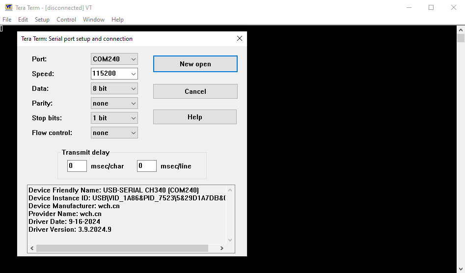
Tera Term의 인터페이스 구성 스크린샷. COM 포트는 환경에 따라 다를 수 있으므로 설정에 맞게 선택해야 합니다.
PC의 터미널 애플리케이션을 연결한 후, 노브를 돌리면 값 문자열을 수신하고 표시하기 시작해야 합니다.
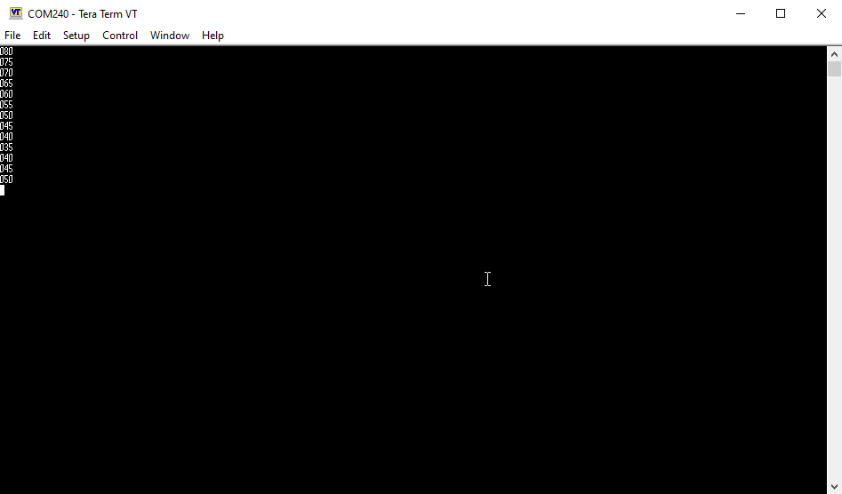
Tera Term에서 수신된 값 문자열의 스크린샷
7단계: UART로부터 데이터 수신하기
이 단계에서는 PC로부터 UART 명령을 수신할 때 애플리케이션이 반응하도록 구현합니다. 간단한 프로토콜에 따라 다음과 같이 진행합니다.
| 명령 | 액션 |
|---|---|
| 'q' | Wi-Fi 아이콘 숨기기 |
| 'w' | Wi-Fi 아이콘 표시 |
| 'e' | 알람 아이콘 숨기기 |
| 'r' | 알람 아이콘 표시 |
프로젝트 템플릿의 Core/Src/knob_interface.hpp에 UART 데이터 수신 함수가 있습니다.
Core/Src/knob_interface.hpp
public:
...
uint8_t knobUartReceiveByte(uint8_t* data);
...
이 함수는 새 데이터가 수신되었을 때 true를 반환하고, 실제 바이트를 지정된 포인터에 복사합니다. 이 함수는 ToucHGFX 애플리케이션의 각 틱 주기마다 UART 수신 버퍼를 폴링하는 데 사용합니다. 이를 위해 먼저 틱 주기마다 메서드를 호출하는 TouchGFX 인터랙션을 추가해야 합니다.
| 상호작용 | 속성 |
|---|---|
| UART 통신 폴링 |
|
이제 다음 코드를 추가하여 UART를 읽고 위 프로토콜을 구현합니다.
TouchGFX/gui/include/gui/screen1_screen/Screen1View.hpp
public:
...
    virtual void toggleLock();
    virtual void decrementValue();
    virtual void incrementValue();
    void changeValue(int change);
    virtual void receiveUartCommand();
TouchGFX/gui/src/screen1_screen/Screen1View.cpp
void Screen1View::receiveUartCommand()
{
#ifndef SIMULATOR
    uint8_t data;
    if (knobUartReceiveByte(&data))
    {
        switch (data)
        {
        case 'q':
            wifiImage.setVisible(false);
            wifiImage.invalidate();
            break;
        case 'w':
            wifiImage.setVisible(true);
            wifiImage.invalidate();
            break;
        case 'e':
            alarmImage.setVisible(false);
            alarmImage.invalidate();
            break;
        case 'r':
            alarmImage.setVisible(true);
            alarmImage.invalidate();
            break;
        }
    }
#endif
}
업데이트된 애플리케이션을 실행하면 위 표에 정의된 프로토콜에 따라 디스플레이의 두 아이콘을 표시하거나 숨길 수 있습니다. 이전 단계에서 사용한 동일한 터미널 프로그램으로 이를 테스트할 수 있습니다. 여기서는 연결된 터미널 프로그램 창을 선택한 후 키보드에서 q, w, e, r 키를 클릭하기만 하면 명령을 전송할 수 있습니다.
이 단계로 튜토리얼 7이 끝납니다.