Tutorial 7: Creating an Application for TSD knob display
In this tutorial, we will create and load an application for the TSD TSS013004A-AD display knob module. This is a graphics entry-level 1.3” round display module based on STM32C091 + 8 MB external flash, running partial framebuffer. The application will have a simple GUI and show how to use the interfaces of the display module (physical controls, ambient light, and UART communication). The MCU platform in the TSD TSS013004A-AD display knob module has the following specifications:
- 48 MHz CPU (STM32C091)
- 36 kB internal SRAM
- 256 kB internal flash
- 8 MB external serial flash
- 24 MHz SPI display interface
To follow this tutorial, Tutorial 1 and Tutorial 2 are recommended prerequisites.
Step 1: Starting a TouchGFX Project
In TouchGFX Designer, an application template (TBS) is provided for the display module, which sets up all the basic functionality. Create a new project based on this:
- Under the "Create" tab, select the board called "TSDHD TSS013-1".
- Set the "Application Name" to e.g. "KnobApplication".
- Click "Create".
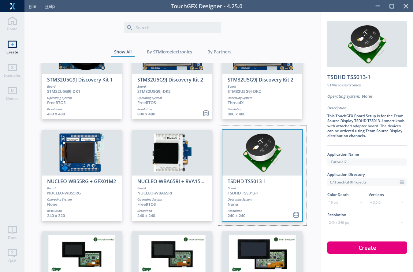
Creating a project for the display module
Step 2: Building a Basic GUI
After creating the project, we have a blank 240 x 240 pixels canvas. In this step, we will design the GUI for our application. It will have a single screen (Screen1) looking like this:

Screenshot of the GUI built in this tutorial
The image assets for this can be downloaded from this link. Unzip the file to the TouchGFX/assets/images folder in your project. To create the GUI, add and configure widgets in TouchGFX Designer according to this table:
| Order | Widget | Name | Properties |
|---|---|---|---|
| 1 | Image | backgroundImage |
|
| 2 | CircleProgress | valueCircleProgress |
|
| 3 | Image | wifiImage |
|
| 4 | Image | alarmImage |
|
| 5 | Image | unlockedImage |
|
| 6 | Image | lockedImage |
|
Step 3: Programming the Application to the Display
Now we will program the preliminary application to the display module to see the GUI on the display. All Discovery Kits and NUCLEO boards made by STMicroelectronics have ST-LINK hardware on board, which is normally used to program applications to these. This third-party display module does not have a built-in ST-LINK. Instead, it can be programmed using the following two alternative methods.
Programming using UART
The display module adapter board has a USB-to-UART chip, which enables communication between the PC and the MCU inside the display module. It is also possible to program the display module this way, utilizing the UART interface of the MCU bootloader. This is the method used by the makefile in this project, when clicking "Run target" in TouchGFX Designer. For the "Run target" script in this project to work, it has the following requirements:
- Display module is connected to the PC through a data USB cable.
- STM32CubeProgrammer (v2.18.0 or later) is installed in the default location.
- Driver for the USB-to-UART is installed. Can be downloaded here: https://www.wch-ic.com/downloads/ch341ser_exe.html.
- The nBOOT_SEL option byte in the MCU must be set to FALSE. This is default in the delivered modules.
After clicking "Run target" and waiting for the compilation and programming to complete, the GUI from Designer canvas should be visible on the module display.
Tip
Further reading
- Reboot the MCU into the built-in bootloader by pulsing RESET and BOOT0 pin on the MCU.
- Program a custom bootloader to MCU RAM (based on ST OpenBootloader) and execute it, to be able to program external flash.
- Program the TouchGFX application to the internal flash of the MCU and the external flash.
- Reboot the MCU into the TouchGFX application by pulsing RESET pin on the MCU.
Programming using external ST-LINK
Another way to program the module is by using an external debugger with wire connections to the pins on the display module adapter board. When using an ST-LINK/V2 debugger it needs wire connections like shown in the table below.
| ST-LINK/V2, 20-pin connector | Knob adapter board |
|---|---|
| 1 | 5V |
| 4 | GND |
| 7 | SWD |
| 9 | SWC |
To be able to also load the external flash using ST-LINK and STM32CubeProgrammer, an External Loader file is provided in the project in Loading/TSDHD-TSS013-1.stldr.
One advantage of using an ST-LINK is that it besides programming also enables debugging of the running application, e.g. using STM32CubeIDE.
An external ST-LINK is not required to follow this tutorial.
Step 4: Add Interactions to Physical Inputs
The display knob module has three physical user input mechanisms: turn left, turn right, and press. In this step, we will make the GUI change the value of the CircleProgress when the knob is turned and toggle screen lock on/off when it is pressed.
The code in TouchGFX/target/KeySampler.cpp reads the hardware inputs and maps them to different key IDs. These can be used to trigger "Hardware button" interactions in TouchGFX Designer as shown below.
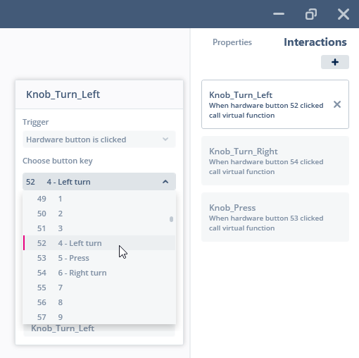
How to use hardware buttons as inputs in ToucHGFX Designer
Add one interaction for each of the inputs according to the table below.
| Interaction | Properties |
|---|---|
| Knob_Turn_Left |
|
| Knob_Turn_Right |
|
| Knob_Press |
|
After adding the interactions and generating code in TouchGFX Designer, code that calls the specified virtual functions is now generated in TouchGFX/generated/gui_generated/src/screen1_screen/Screen1ViewBase.cpp. To implement our desired functionality we therefore need to add them (and a helper function) to our user code screen class header file:
TouchGFX/gui/include/gui/screen1_screen/Screen1View.hpp
public:
...
    virtual void toggleLock();
    virtual void decrementValue();
    virtual void incrementValue();
    void changeValue(int change);
And implement them in our user code screen class source file:
TouchGFX/gui/src/screen1_screen/Screen1View.cpp
void Screen1View::toggleLock()
{
    lockedImage.setVisible(!lockedImage.isVisible());
    lockedImage.invalidate();
}

void Screen1View::decrementValue()
{
    if (!lockedImage.isVisible())
    {
        changeValue(-5);
    }
}

void Screen1View::incrementValue()
{
    if (!lockedImage.isVisible())
    {
        changeValue(5);
    }
}

void Screen1View::changeValue(int change)
{
    const int newValue = valueCircleProgress.getValue() + change;
    valueCircleProgress.updateValue(newValue, 0);
}
The display module can now be programmed with the updated application. You can now press the knob to unlock the GUI and afterwards turn the knob to change the value of the CircleProgress.
Tip
Step 5: Control the LED Ambient Light
The display knob module has a ring of red, green and blue LEDs which can be turned on for ambient light around it. Each color channel is controlled with a PWM capable output from the MCU. In the application template we are using, a function for controlling this light is implemented in Core/Inc/knob_interface.cpp and avilable through Core/Src/knob_interface.hpp:
Core/Src/knob_interface.hpp
public:
...
void knobSetAmbientLightRGB(uint8_t red, uint8_t green, uint8_t blue);
...
In this demo, we will control the color of the light based on the value of the CircleProgress. We will do this such that the light is blue when the value is zero and gradually turning red through purple as the value increases. This can be done by adding the following code to Screen1View:
TouchGFX/gui/src/screen1_screen/Screen1View.cpp
#include <gui/screen1_screen/Screen1View.hpp>
#ifndef SIMULATOR
#include "knob_interface.hpp"
#endif

void Screen1View::setupScreen()
{
    Screen1ViewBase::setupScreen();
    changeValue(0); // Ensure that the system state is synchronized at start-up
}

void Screen1View::changeValue(int change)
{
    const int newValue = valueCircleProgress.getValue() + change;
    valueCircleProgress.updateValue(newValue, 0);

#ifndef SIMULATOR
    const int value = valueCircleProgress.getValue(); // Always inside the range set in TouchGFX Designer (0-100)

    //Update ambient light
    const uint8_t red = (value * 255) / 100;
    const uint8_t green = 0;
    const uint8_t blue = 255 - red;
    knobSetAmbientLightRGB(red, green, blue);
#endif
}
When running the application on the display module, it will now activate the ambient light and change the color when the knob is unlocked and turned.
Tip
Step 6: Send Data on UART
The knob display module has a UART communication interface and 6 GPIOs (PA0-5) externally available through the connector cable. In this step, we will make the application transmit an ASCII string on the UART every time the value of the CircleProgress is updated. The UART interface is configured in the template project for the display module and available through Core/Src/knob_interface.hpp:
Core/Src/knob_interface.hpp
public:
...
void knobUartSendByte(uint8_t data);
void knobUartSendBytes(uint8_t* data, uint16_t size);
void knobUartSendString(uint8_t* data);
...
Here, we will use the knobUartSendByte function multiple times to transmit the different ASCII characters of a string representing the value:
TouchGFX/gui/src/screen1_screen/Screen1View.cpp
void Screen1View::changeValue(int change)
{
    const int newValue = valueCircleProgress.getValue() + change;
    valueCircleProgress.updateValue(newValue, 0);

#ifndef SIMULATOR
    const int value = valueCircleProgress.getValue(); // Always inside the range set in TouchGFX Designer (0-100)

    //Update ambient light
    const uint8_t red = (value * 255) / 100;
    const uint8_t green = 0;
    const uint8_t blue = 255 - red;
    knobSetAmbientLightRGB(red, green, blue);

    // Send new value on UART
    knobUartSendByte('0' + value / 100);
    knobUartSendByte('0' + (value % 100) / 10);
    knobUartSendByte('0' + value % 10);
    knobUartSendByte('\r');
    knobUartSendByte('\n');
#endif
}
When running the application on the display module, it will now transmit data on the UART when the knob is unlocked and turned. This UART data can be received on the PC through the same interface as used for UART programming. To do so, we need a "Terminal application" installed on the PC, e.g. Tera Term or PuTTY. Here is the needed interface configuration done in Tera Term as example:
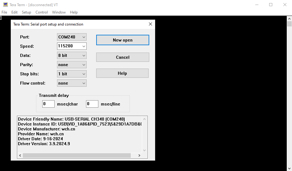
Screenshot of the interface configuration in Tera Term. Note that the COM Port will vary and should be selected to match your setup.
After connecting the terminal application on the PC, it should now start receiving and showing the value strings when the knob is turned:
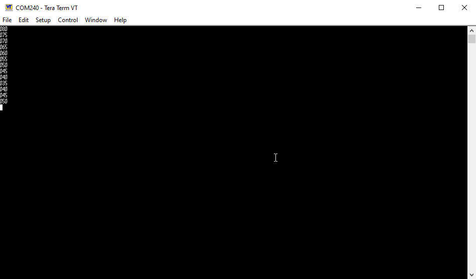
Screenshot of the value strings received in Tera Term
Step 7: Receive Data from UART
In this step, we will make the application react when receiving UART commands from the PC, according to this simple protocol:
| Command | Action |
|---|---|
| 'q' | Hide wifi icon |
| 'w' | Show wifi icon |
| 'e' | Hide alarm icon |
| 'r' | Show alarm icon |
There is a function for receiving UART data available in the project template in Core/Src/knob_interface.hpp:
Core/Src/knob_interface.hpp
public:
...
uint8_t knobUartReceiveByte(uint8_t* data);
...
This function will return true, when new data has been received and copy the actual byte to the given pointer. We will use this function to poll the UART receive buffer in every tick of the ToucHGFX application. To do so, we first need to add a TouchGFX interaction to call a method every tick:
| Interaction | Properties |
|---|---|
| Poll UART communication |
|
We now add the following code to read the UART and implement the above protocol:
TouchGFX/gui/include/gui/screen1_screen/Screen1View.hpp
public:
...
    virtual void toggleLock();
    virtual void decrementValue();
    virtual void incrementValue();
    void changeValue(int change);
    virtual void receiveUartCommand();
TouchGFX/gui/src/screen1_screen/Screen1View.cpp
void Screen1View::receiveUartCommand()
{
#ifndef SIMULATOR
    uint8_t data;
    if (knobUartReceiveByte(&data))
    {
        switch (data)
        {
        case 'q':
            wifiImage.setVisible(false);
            wifiImage.invalidate();
            break;
        case 'w':
            wifiImage.setVisible(true);
            wifiImage.invalidate();
            break;
        case 'e':
            alarmImage.setVisible(false);
            alarmImage.invalidate();
            break;
        case 'r':
            alarmImage.setVisible(true);
            alarmImage.invalidate();
            break;
        }
    }
#endif
}
When running the updated application, it is now possible to hide and show the two icons on the display according to the protocol in the table above. This can be tested with the same terminal program used in the previous step. Here, the commands can simply be sent by selecting the window of the connected terminal program and clicking the q, w, e, and r key on the keyboard.
This step concludes Tutorial 7.