STM32H7R7 및 S7에서 그래픽 실행하기
이 문서는 STM32H7R/S 시리즈 MCU의 특정 아키텍처에 대해 다루고 그래픽에 이를 사용할 경우 고려해야 하는 사항을 설명합니다. 하지만 이러한 고려 사항의 대부분은 외부 RAM 및 플래시를 이용해 그래픽을 실행하는 모든 STM32 MCU에 적용할 수 있습니다.
STM32H7R/S는 고성능 장치이자 고급 MCU이므로 이 문서는 TouchGFX Board Setups(TBS)에 대한 초급자용 가이드가 아닙니다. 따라서 이 문서에서는 STM32H7R/S에만 해당하는 중요한 영역을 심도 있게 다룰 것입니다. TouchGFX TBS를 생성하는 방법에 대한 전반적인 설명은 보드 브링업 가이드를 참조하세요.
STM32H7R7/S7에 대한 자세한 내용은 제품 페이지 또는 STM32H7RS 데모 워크숍 전체가 포함된 YouTube 재생목록을 참조하세요.
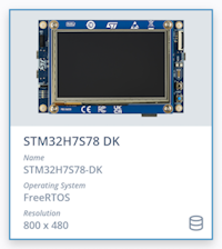
TouchGFX Designer에는 STM32H7R/S에서 TouchGFX를 실행하는 것에 대한 완전한 예제 프로젝트인 STM32H7S78 DK용 TBS가 포함되어 있습니다. TBS는 STM32H7R/S용 TouchGFX 애플리케이션을 개발할 때 참조로 사용할 수 있습니다. 이 프로젝트는 STM32CubeMX를 기반으로 합니다. 즉, STM32H7S78-DK.ioc 파일을 열어 캐시, MPU, 외부 메모리 등에 대한 권장 구성을 확인할 수 있다는 뜻입니다.
메모리 설정
STM32H7R/S는 부트플래시 MCU입니다. 부트플래시 MCU는 부트로더를 포함하는 작은 플래시가 내장된 MCU이며 메인 애플리케이션은 애셋과 함께 외부 메모리에 배치되어 있습니다. 또한 STM32H7R/S에는 620kB의 SRAM도 내장되어 있습니다. 그 결과, STM32H7R/S는 그래픽 애플리케이션에 사용될 때 외부 RAM과 플래시 모두를 사용합니다. 그래픽에 외부 메모리를 사용할 경우 CPU 주파수의 절반이나 1/3로 실행되므로 외부 메모리에 대한 메모리 대역폭에 병목 현상이 발생하는 경우가 많습니다. STM32H7R7/S7의 경우, 2개의 XSPI(16비트 및 8비트) 인터페이스가 두 배의 전송 속도로 최대 200MHz에서 실행될 수 있으며 FMC(16비트 또는 32비트)는 최대 100MHz에서 실행될 수 있습니다.
External Memory Manager
External Memory Manager 및 External Memory Loader라고 불리는 2개의 도구는 STM32CubeMX의 카테고리 → Middleware and Software Packs 아래에서 찾을 수 있습니다. 이러한 도구는 사용자가 부트플래시 또는 플래시 없는 애플리케이션에서 외부 메모리를 설정하는 데 도움이 되도록 고안되었습니다. 이 도구를 이용하면 외부 로더를 만들고 애플리케이션 유형을 선택하는 작업 등을 보다 쉽게 수행할 수 있습니다. 도구에 대한 소개는 여기에서 확인할 수 있습니다. "STM32가 포함된 외부 직렬 메모리 소개"라 불리는 새로운 문서가 곧 발행됩니다.
Further reading
외부 RAM의 프레임 버퍼
외부 RAM에 프레임 버퍼가 있을 때 가장 우선적으로 고려해야 할 중요한 사항은 메모리 대역폭 요구 사항과 제약 조건입니다. GRAM이 탑재되지 않은 디스플레이의 경우 디스플레이에 의해 지정된 속도로 프레임 버퍼를 지속적으로 전송해야 합니다. 디스커버리 키트에서 사용되는 디스플레이의 경우 60Hz입니다. 외부 RAM 인터페이스의 대역폭에서 상당 부분이 LTDC 업데이트에만 사용된다는 뜻입니다. LTDC에 필요한 대역폭은 다음과 같이 계산할 수 있습니다:
픽셀 클록 = LCD_CLK= 전체 스크린 크기 * 주사율
필요한 대역폭(LTDC 계층 1개에 대해) = LCD_CLK * Bpp
또한 DMA2D 및 GPU2D도 프레임 버퍼에서 작업을 수행할 때는 외부 RAM의 대역폭이 필요합니다. 메모리가 애플리케이션 코드 등의 다른 데에도 사용되는 경우에는 대역폭이 더욱 줄어듭니다.
이러한 요인이 결합되어 외부 RAM 버스가 혼잡해질 수 있습니다.
외부 RAM의 프레임 버퍼를 이용해 그래픽을 실행할 때 고려해야 할 사항을 설명하는 문서는 여기에서 확인할 수 있습니다.
외부 RAM에 LTDC 디스플레이 인터페이스와 프레임 버퍼가 있는 경우에 고려해야 할 사항과 제약 조건에 대한 자세한 내용은 LTDC 애플리케이션 노트를 참조하세요. 챕터 5: "LTDC로 그래픽 애플리케이션 만들기"와 챕터 7: "LTDC 애플리케이션 예제"를 특히 주의하여 살펴보시기 바랍니다.
외부 RAM의 대역폭이 한계에 도달했다면 챕터 5.5.2: "외부 메모리에서 LTDC 프레임 버퍼 가져오기 최적화" 및 챕터 5.5.3: "SDRAM에서 LTDC 프레임 버퍼 가져오기 최적화"를 고려해 보세요.
Further reading
TCM(Tightly coupled memory)
STM32H7R/S Cortex-M7은 대기 상태 없이 TCM(Tightly coupled memories)에 64-bit 폭의 직접 액세스를 제공합니다. 최대 192 kB의 데이터 TCM(DTCM)과 명령어 TCM(ITCM)을 탑재할 수 있습니다. 따라서 DTCM과 ITCM은 각각 데이터 읽기/쓰기와 명령 가져오기에 최적의 위치입니다. 그러므로 ITCM은 캐시 미스에 민감한 인터럽트 핸들러나, 실시간성이 중요한 제어 루프와 같은 결정적 실행이 필요한 핵심 코드에 사용하는 것이 바람직합니다. RTOS를 사용하는 실시간 애플리케이션에서는 일반적으로 heap이 많이 사용됩니다. 따라서 DTCM에 RTOS stack과 heap을 배치하는 것이 좋습니다. 남은 공간이 있다면 여기에 전역 변수도 배치할 수 있습니다.
ITCM와 DTCM이 SRAM1 및 SRAM3 메모리의 일부를 사용한다는 것을 인지하는 것이 중요합니다. 이는 ITCM과 DTCM을 사용할 때는 내부 SRAM의 크기가 줄어든다는 것을 시사합니다.
다른 H7 MCU와 마찬가지로, STM32H7R/S에는 Level 1(L1) 캐시가 있습니다. L1 캐시에 대한 자세한 내용은 H7 캐시 애플리케이션 노트를 참조하세요. 특히 챕터 4: "피해야 할 실수 및 팁"을 주의 깊게 살펴보세요.
외부 SPI 메모리를 설정하는 방법에 대한 상세한 설명은 OSPI, HSPI 및 XSPI 애플리케이션 노트를 참조하세요.
Further reading
애플리케이션 유형
시작하는 동안 부트로더는 선택한 애플리케이션 유형에 따라 다양한 작업을 수행할 수 있습니다. 이미 외부 플래시에 있는 애플리케이션을 가리킬 수도 있고 아니면 다른 메모리(일반적으로 외부 RAM)에 애플리케이션을 로드할 수도 있습니다.
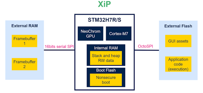
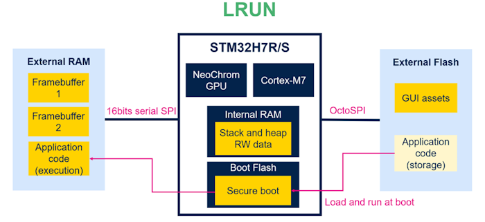
이미 외부 플래시에 있는 애플리케이션을 실행하는 것을 XiP(execute-in-place)라고 부릅니다. 부팅 중에 플래시에서 RAM으로 애플리케이션을 복사한 다음 RAM에서 실행하는 것은 LRUN(load-and-run)이라 부릅니다.
애플리케이션이 암호화된 경우에는 LRUN만 사용할 수 있습니다. STM32에서의 암호화에 대한 자세한 내용은 암호화에 대한 애플리케이션 노트를 참조하세요.
XiP(Execute in Place)
그래픽 애플리케이션에서 XiP의 메모리 레이아웃 예시는 아래에 소개되어 있습니다. XiP는 기본 애플리케이션 유형입니다.
XiP 이미지에서 볼 수 있듯이 외부 플래시에 대한 OctoSPI 인터페이스는 애플리케이션 코드와 그래픽 애셋에 액세스하는 데 사용됩니다. CPU가 애플리케이션에 지속적으로 액세스하므로 이로 인해 애셋에 액세스할 때 NeoChrom GPU 또는 Chrom-ART의 액세스 속도가 느려질 수 있습니다. 이는 그래픽 성능에 부정적인 영향을 미칩니다. 이 문제를 완화하려면 XiP를 실행할 때 외부 플래시에 대한 명령 캐시를 활성화하는 것이 좋습니다. 이렇게 하면 반복된 명령을 외부 플래시 대신 캐시에서 읽어올 수 있어 대역폭에 대한 부하를 줄이고 외부 플래시 인터페이스의 효율성을 높일 수 있습니다.
LRUN(Load and Run)
LRUN에 해당하는 예제는 아래에 나와 있습니다.
LRUN 이미지에서 볼 수 있듯이 이제 애플리케이션 코드가 그래픽 애셋으로부터 분리되어 애셋에 대한 액세스가 향상되었습니다. 하지만 프레임 버퍼와 애플리케이션 코드 모두에 액세스하는 데 필요하므로 외부 RAM에 대한 인터페이스가 로드될 것임을 의미하기도 합니다. 이 경우 외부 RAM 인터페이스에서 명령 캐시를 활성화하는 것을 적극 권장합니다.
그래픽 애플리케이션과 함께 STM32H7R/S에서 LRUN을 사용할 경우 가능한 한 최상의 성능을 달성하기 위해 고려해야 할 몇 가지 추가 사항이 있습니다.
첫째, 애셋(비트맵, 글꼴 등)을 외부 플래시에 보관할 수 있을지 고려합니다. 애셋에 자주 액세스하므로 이를 외부 RAM에 보관하면 외부 RAM의 대역폭에 상당한 부하를 가하게 됩니다. 게다가 일반적으로 애셋을 암호화할 필요가 없습니다.
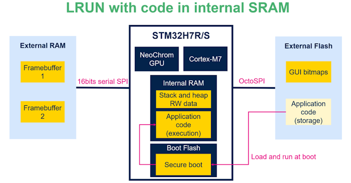
둘째, 아래에서 보이는 바와 같이 애플리케이션 코드가 내부 SRAM에 적합한지 검토해 볼 가치가 있습니다. 내부 버스가 더 빠르기 때문에 애플리케이션 코드는 외부 플래시나 외부 RAM에 두는 것보다 내부 SRAM에 있어야 더 빠르게 액세스 및 실행할 수 있습니다. 내부 SRAM이 연결된 STM32H7R/S의 AXI 버스는 최대 300MHz의 속도로 실행될 수 있습니다. 또한 이 구성을 이용하면 애셋, 프레임 버퍼, 애플리케이션을 서로 다른 3개의 위치에 배치할 수 있으므로 3개의 개별 버스에 대역폭 부하를 분산할 수 있습니다.
성능 비교
다음은 각각 XiP와 LRUN을 사용하는 복잡한 GUI의 예제입니다. LRUN 애플리케이션은 내부 SRAM에 애플리케이션 코드가 있습니다. 비교는 다양한 구성이 MCU 부하에 어떤 영향을 미치는지 보여줍니다. 내부 SRAM에 TouchGFX 프레임워크와 애플리케이션을 배치하면 외부 RAM과 플래시를 가져오는 주기 횟수가 감소하며 이에 따라 MCU 부하가 효과적으로 줄어듭니다.
데모 참조는 STM32H7S78-DK에서 실행되는 기본 데모입니다.
이 비교는 애플리케이션 코드가 내부 SRAM에 배치될 경우 MCU 부하가 줄어든다는 것을 보여줍니다. XiP에 비해 LRUN을 사용할 때 MCU 부하가 약 50% 줄어들었습니다.
이 비교는 애플리케이션 코드가 내부 SRAM에 배치될 때 MCU 부하가 대폭 줄어든다는 것을 보여줍니다. 이는 외부 RAM 및 플래시에 비해 내부 SRAM의 액세스 시간이 훨씬 짧기 때문입니다. 애플리케이션 코드가 XiP에 있을 때에 비해 내부 SRAM에 있는 상태에서 LRUN을 사용할 경우 MCU 부하가 50% 감소했습니다. 애플리케이션 코드가 내부 SRAM에 저장된 상태에서 LRUN을 사용하면 최상의 성능을 얻을 수 있습니다. 하지만 이 구성은 애플리케이션 코드가 사용 가능한 내부 SRAM에 적합한 경우에만 실현 가능합니다.
MPU 구성
메모리 보호 장치(MPU)는 의도치 않은 메모리 액세스 및 실행으로부터 메모리 영역을 보호하는 데 사용됩니다.
Arm® Cortex®-M7 프로세서에서는 외부 메모리에서 수행될 때 긴 지연 시간이나 시스템 오류가 발생할 수 있으므로 추측성 액세스를 방지하는 것이 중요합니다. STM32H7R/S의 경우, 이것이 메모리에 액세스하는 AXI 마스터에 영향을 미치며 그래픽 성능도 현저히 저하시킵니다.
MPU는 액세스 가능한 주소 범위를 제어함으로써 추측성 읽기 액세스를 방지하는 데 사용될 수 있습니다. 이를 수행하는 가장 쉬운 방법은 전체 메모리 영역과 함께 백그라운드 영역을 사용하는 것입니다. 이를 "strongly ordered, execute never"로 설정해 액세스를 제한할 수 있습니다.
다른 모든 영역이 이 영역보다 우선순위가 높아지므로 백그라운드 영역은 ID-1인 기본 영역에서 정의되어야 합니다. 그런 다음, 각각의 설정을 가진 다른 MPU 영역이 액세스가 필요한 메모리 영역에 대해 정의되어야 합니다. STM32H7R/S에서는 최대 16개의 영역을 정의할 수 있습니다.
STM32H7S78 DK TBS의 MPU 구성이 아래에 삽입되었습니다. 이 구성은 참조로 사용할 수 있습니다.
| 영역 0 | 모두 | 참고 |
|---|---|---|
| 속성 | 값 | |
| MPU 영역 기반 주소 | 0x0 | |
| MPU 영역 크기 | 4GB | MCU의 전체 메모리 영역을 포함 |
| MPU 하위 영역 비활성화 | 0x0 | |
| MPU TEX 필드 수준 | Level 0 | |
| MPU 액세스 권한 | 일부 액세스는 허용되지 않음 | 모든 액세스 제한 |
| MPU 명령 액세스 | 비활성화 | |
| MPU 공유 가능성 권한 | 활성화 | |
| MPU 캐싱 가능한 권한 | 비활성화 | |
| MPU 버퍼링 가능 권한 | 비활성화 |
| 영역 1 | 외부 플래시 | 참고 |
|---|---|---|
| 속성 | 값 | |
| MPU 영역 기반 주소 | 0x70000000 | XSPI2(외부 플래시)의 기본 주소 |
| MPU 영역 크기 | 128MB | 보드의 128MBytes 외부 플래시 |
| MPU 하위 영역 비활성화 | 0x0 | |
| MPU TEX 필드 수준 | Level 1 | |
| MPU 액세스 권한 | 모든 액세스 허용 | |
| MPU 명령 액세스 | 비활성화 | |
| MPU 공유 가능성 권한 | 비활성화 | |
| MPU 캐싱 가능한 권한 | 활성화 | |
| MPU 버퍼링 가능 권한 | 활성화 |
| 영역 2 | 외부 플래시 | 참고 |
|---|---|---|
| 속성 | 값 | |
| MPU 영역 | 활성화됨 | |
| MPU 영역 기반 주소 | 0x70000000 | XSPI2(외부 플래시)의 기본 주소 |
| MPU 영역 크기 | 2MB | 애플리케이션 코드가 배치된 외부 플래시의 첫 2MB에 대한 속성이 덮어쓰기됨 |
| MPU 하위 영역 비활성화 | 0x0 | |
| MPU TEX 필드 수준 | Level 1 | |
| MPU 액세스 권한 | 모든 액세스 허용 | |
| MPU 명령 액세스 | 활성화 | |
| MPU 공유 가능성 권한 | 비활성화 | |
| MPU 캐싱 가능한 권한 | 활성화 | |
| MPU 버퍼링 가능 권한 | 활성화 |
| 영역 3 | 외부 PSRAM | 참고 |
|---|---|---|
| 속성 | 값 | |
| MPU 영역 기반 주소 | 0x90000000 | XSPI1(외부 PSRAM)의 기본 주소 |
| MPU 영역 크기 | 32MB | 보드의 32MBytes 외부 PSRAM |
| MPU 하위 영역 비활성화 | 0x0 | |
| MPU TEX 필드 수준 | Level 1 | |
| MPU 액세스 권한 | 모든 액세스 허용 | |
| MPU 명령 액세스 | 비활성화 | |
| MPU 공유 가능성 권한 | 비활성화 | |
| MPU 캐싱 가능한 권한 | 비활성화 | |
| MPU 버퍼링 가능 권한 | 비활성화 |
| 영역 4 | DTCM | 참고 |
|---|---|---|
| 속성 | 값 | |
| MPU 영역 기반 주소 | 0x20000000 | DTCM의 기본 주소 |
| MPU 영역 크기 | 64kB | 기본 64kB의 DTCM |
| MPU 하위 영역 비활성화 | 0x0 | |
| MPU TEX 필드 수준 | Level 1 | |
| MPU 액세스 권한 | 모든 액세스 허용 | |
| MPU 명령 액세스 | 비활성화 | |
| MPU 공유 가능성 권한 | 비활성화 | |
| MPU 캐싱 가능한 권한 | 비활성화 | 성능 향상을 제공하지 않으므로 DTCM에서의 캐싱 비활성화 |
| MPU 버퍼링 가능 권한 | 비활성화 |
| 영역 5 | SRAM | 참고 |
|---|---|---|
| 속성 | 값 | |
| MPU 영역 기반 주소 | 0x24000000 | SRAM1의 기본 주소 |
| MPU 영역 크기 | 512kB | SRAM1, SRAM2, SRAM3, SRAM4 포함 |
| MPU 하위 영역 비활성화 | 0x0 | |
| MPU TEX 필드 수준 | Level 1 | |
| MPU 액세스 권한 | 모든 액세스 허용 | |
| MPU 명령 액세스 | 비활성화 | |
| MPU 공유 가능성 권한 | 활성화 | |
| MPU 캐싱 가능한 권한 | 활성화 | |
| MPU 버퍼링 가능 권한 | 활성화 |
| 영역 6 | GPU2D 명령 목록 | 참고 |
|---|---|---|
| 속성 | 값 | |
| MPU 영역 기반 주소 | 0x2406e000 | 여기에 NeoChrom GPU 명령 목록이 배치되어 있음 |
| MPU 영역 크기 | 16kB | TouchGFX를 사용할 때 NeoChrom GPU 명령 목록의 기본 크기(nema_hal.c에 정의됨) |
| MPU 하위 영역 비활성화 | 0x0 | |
| MPU TEX 필드 수준 | Level 0 | |
| MPU 액세스 권한 | 모든 액세스 허용 | |
| MPU 명령 액세스 | 비활성화 | |
| MPU 공유 가능성 권한 | 활성화 | |
| MPU 캐싱 가능한 권한 | 비활성화 | 명령 목록에서 캐싱 비활성화 |
| MPU 버퍼링 가능 권한 | 활성화 |
일반적인 그래픽별 MPU 구성 팁에 대해서는 LTDC 애플리케이션 노트의 챕터 5.6.2: "메모리 보호 장치(MPU) 구성"을 참조하세요.
자세한 내용은 MPU 애플리케이션 노트를 참조하세요. 특히 챕터 3: "Cortex-M0+/M3/M4/M7 메모리 유형, 등록 및 속성" 및 챕터 6: "Armv6 및 Armv7 아키텍처에서 STM32Cube HAL을 이용한 MPU 설정 예시"를 주의 깊게 살펴보세요.
Further reading
디버깅
STM32CubeIDE에서 STM32H7R/S를 디버깅하는 것에 대한 다음 가이드는 TouchGFX Designer에서 제공되는 TBS의 readme에서 확인할 수 있습니다.
STM32H7S78-DK에 대한 TBS의 부트로더와 애플리케이션 구조로 인해 IDE의 코드를 디버깅하는 것은 복잡한 일일 수 있습니다. STM32CubeIDE의 TouchGFX 애플리케이션 코드의 단계를 살펴보려면 다음 단계를 따르세요:
- TouchGFX Designer에서 코드 생성
- STM32CubeIDE에서 프로젝트를 엽니다.
- 부트 프로젝트에 대한 디버그 세션을 시작합니다.
- 컴파일 및 플래싱이 완료될 때까지 기다립니다.
- 디버그 세션을 종료합니다(Ctrl + F2).
- Appli 프로젝트에 대한 디버그 세션을 시작합니다.
- 컴파일 및 플래싱이 완료될 때까지 기다립니다.
- Resume(F8)을 클릭합니다.
- STM32H7S78-DK 보드에서 검은색 NRST 버튼을 누릅니다.
- 애플리케이션은 이제 Appli 프로젝트의 첫 번째 main() 줄의 중단점에 있습니다. 그렇지 않다면 Resume(F8)을 한 번 더 누르세요.
- Resume(F8) 또는 Step Over(F6)를 클릭해 계속합니다.
디버깅에 대한 자세한 내용은 STM32H7RS에서 DA 액세스를 시작하는 방법에 대한 wiki 페이지를 참조하세요.
Further reading
그래픽 애플리케이션에 대한 결론 및 일반적인 권장 사항
위에 설명된 바와 같이 STM32H7R/S용 그래픽 애플리케이션을 개발할 때 고려해야 할 몇 가지 사항이 있습니다. 하지만 이러한 고려 사항을 염두에 두고 작업한다면 빠른 CPU와 강력한 GPU2D를 통해 우수한 그래픽 성능을 달성할 수 있습니다.
우선, 외부 메모리 버스의 대역폭을 인지하는 것이 매우 중요합니다. 이는 외부 RAM 및 플래시와 함께 사용되는 모든 MCU에 적용되지만, STM32H7R/S의 부트플래시 구조로 인해 특히 중요한 고려 사항입니다.
중요한 명령과 데이터를 ITCM 및 DTCM 메모리에 배치하면 성능을 상당히 향상할 수 있습니다.
Arm® Cortex®-M7 프로세서에 L1 명령과 데이터 캐시를 통합하는 것을 통해서도 성능을 향상할 수 있습니다.
애플리케이션 요구 사항에 따라 XiP 또는 LRUN 중에서 선택해서 실행하되 메모리 대역폭에 유의해야 한다는 점을 기억하세요. 애플리케이션 코드가 내부 SRAM에 적합하다면, LRUN이 최상의 성능을 제공할 것입니다.
추측성 읽기 액세스는 잠재적으로 성능을 대폭 저하시킬 수 있으므로 피해야 합니다. 이는 모든 메모리 영역에 적합한 MPU 구성을 적용하는 것을 통해 수행할 수 있습니다.


