Display
Products are getting richer with enhanced user experiences, embedding newer larger displays, and replacing older segment displays with low and high color displays.
This chapter focuses on some considerations that should be included when selecting the right display for your embedded GUI product.
Different types of displays
Note
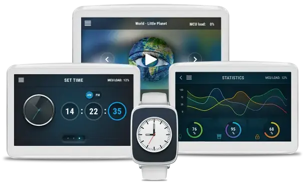
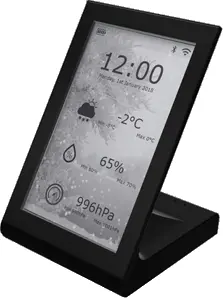
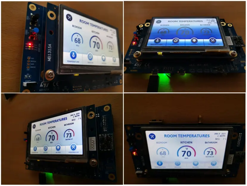
Examples of Displays
Selecting the right display technology can be complicated as key factors in each display are different. The following chapter is high-level addressing the different technologies, and can hopefully help you in the right direction.
Each kind of display consists of rows and columns of pixels, which can be driven in different ways, having internal and/or external display controller and RAM for framebuffers. In some technologies, each pixel needs to be updated frequently compared to other technologies where this is not necessary, as updates only happens when something changes in the GUI.
There is a vast amount of different display technologies. Some of the most used display technologies are described in the following.
LCD-TFT
TFT stands for thin-film-transistor and is a variant of LCD displays with an active matrix. LCD-TFTs are widely used in embedded products as they are available in many different resolutions, sizes, interfaces, price ranges, etc.
Some variants of TFT-LCDs are TN and IPS panels. Examples of IPS TFT-LCDs, is the STM32F769 DISCO and STM32H747 DISCO, both running a 800*480 MIPI-DSI TFT IPS LCD display. Examples of TFT-LCD TN displays are the STM32F746G DISCO and STM32H7B3I-DK. Both technologies come in different qualities, but some differences can be the color presentation and viewing angles, where IPS panels often are the best.

LCD-TFT layers example
MIP
MIP means memory in pixels, which uses a pixel technology which only needs power/data when something changes on the screen. MIP displays are low power and runs low to full color GUIs.
ePaper/eInk
eInk displays are low color displays, ideal for applications with low power consumption needs, wide viewing angles, and easy readability. TouchGFX Implementer SDATAWAY demonstrates an eInk display running an TouchGFX application on a STM32F412 here: https://www.st.com/resource/en/brochure/BRSTM32TGFX0721_web.pdf
E-Ink
Display Interface Overview
The display is connected to the MCU through a variety of interfaces. TouchGFX is compatible with any display interface, and STM32 microcontrollers support a broad spectrum of options, including Motorola 6800, Intel 8080, SPI, RGB-TFT, and MIPI-DSI interfaces. These display interfaces vary based on multiple parameters, and the table below offers a basic overview of each.
| Interface | # of data pins** | Maximum recommended resolution* | Advantages | Disadvantages |
|---|---|---|---|---|
| SPI | 2 | 480*272 | Simple hardware interface | Relatively low bandwidth |
| Parallel 8080/6800 (FMC) | 8/16 | 480*320 | Simple hardware interface, faster than SPI | High pin count, bandwidth lower than RGB-TFT |
| RGB-TFT (LTDC) | 8/18/24 | 1280*800 | High performance, low cost | High pin count, parallel communication can cause EMC issues -> limited cable length, can require higher clock frequency |
| MIPI-DSI [Command mode] (LTDC) | 4/10 | 800*480 | High performance, low pin count | Complex protocols and drivers, requires more GRAM to support heigher resolutions |
| MIPI-DSI [Video mode] (LTDC) | 4/10 | 1280*800 | High performance, low pin count, similar to RGB-TFT | Complex protocols and drivers, requires higher clock frequency |
| LVDS | - | 1366*768 | Low EMC issues -> supporting longer cables, high speed | A bridge is required for interfacing with a LVDS display |
- * These are the display resolutions recommended for TouchGFX to achieve the intended performance
- ** Additional pins might be needed for clock signal, touch functionality, power, controls signals, etc.
For more specific details about the LCD-TFT display controller (LTDC), you can refer to this document.
Brightness and Backlight
Brightness is often measured in candela/m². Backlights can be the most power consuming part of the display. In sunlight one would need around 600 cd/M2. Often higher brightness increases the temperature, minimizing the lifetime of the LEDs.
Viewing Position and Color Inversion
When embedding a display into a product, it is important to anticipate and know which viewing positions the user can have. In some displays from certain viewing positions, a color inversion can happen. This means that installing the display in the right position, allowing the user to operate and experience the GUI while seeing the right colors designed by the graphics designer, can be tricky.
The color inversion can happen on TN panels. Adding a SWV film can help increasing viewing angles.
Resulting colors from different viewing position
Display Lifetime
The lifetime is defined as the time until the display reaches half brightness at 25 degrees. If your product has a long life cycle, then this parameter must be taken into consideration.
Pixel density
Pixel density defines how many pixels are shown per inch or square inch. Choosing the right pixel density can depend on the expectations from the end user, environment, design needs etc. Putting this into perspective, a high-end mobile phone runs a 6.1” 2340x1080 with a pixel density per square inch of 178.500, while a commonly used 5” TFT display running 800x480 has 34.816 Pixels per square inch.
Low, medium and high pixel density
Some standard resolutions, display sizes and pixel densities measured in pixels per square inch (PPI2):
| QVGA 320*240 | 2.4” (27,777 PPI2) | 3.5” (13,061 PPI2) |
| WQVGA 480*272 | 4,3” (16,462 PPI2) | 5” (12,175 PPI2) |
| HVGA 480*320 | 3.5” (27,167 PPI2) | |
| VGA 640*480 | 5,7” (19,698 PPI2) | 6.4 (15,625 PPI2) |
| WVGA 800*480 | 4” (54,400 PPI2) | 5” (34,816 PPI2) |
| WSVGA 1024*600 | 7” (28,746 PPI2) | 10,1” (13,808 PPI2) |
For some applications it can be difficult seeing any difference, unless the display is being looked at very closely. Examples of pixels densities are: STM32F476DISCO with 16.462 PPI2 and STM32F769DISCO with 54.400 PPI2.
The example above of different pixel densities can in some cases impact the dynamic color range and anti-aliasing:
Dynamic color range
The dynamic color range is the ratio between two contrasting colors, like black and white. In the example above, the blue and white contains different levels of white and blue. The image on the left has lower pixel density, and the picture on the right has more pixels to show all the colors represented, creating a smoother transition between different colors and edges.
Anti-aliasing
When the pixel density is too low, a staircase effect can appear. Using anti-aliasing in the application can smooth out these staircase edges in an image. When looking at the first two blue circles, the staircase effect appears, as the pixel density does not allow the display to represent enough pixels to have a high enough color range enabling high enough anti-aliasing.
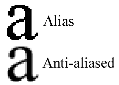
Anti-aliasing
Environment
When deciding which display to use, the environment is a vital part to consider. Some questions to ask yourself are:
- Is the display in direct sunlight?
- Is it being used in rugged environments where it needs to be impact resistent?
- Is it being handled by one wearing gloves?
- Does it need vandal proofing?
- Is it being operated with physical buttons only?
Answering these questions will give you an better idea of which touch technology to select or even if touch is required.
Note
Touch / Non-touch displays
There are different touch technologies available in the market today and some examples are: resistive, capacitive (surface, projected), SAW touch, infrared touch. This section will only address some of these technologies:
Capacitive Touch
This is one of the most popular touch technologies. It comes in two sensing technologies:
- Self capacitance is for single finger touch
- Mutual capacitance allowing multi touch but more challenged when exposed to water/moist (TouchGFX does not support multi touch).
Most STM32 DISCO boards are using capacitive touch, some examples are the STM32H7B3I DISCO, STM32H750 DISCO, STM32F746G DISCO.
Resistive Touch
Resistive touch is a simple technology activated by mechanical pressure, and only requires ADC - or a simple touch controller. It is often low price due to maturity. The surface is more protected to scratches and tearing, so more difficult to vandal proof. It also has lower sunlight readability. The STM32F429 DISCO board uses resistive touch, available with a TouchGFX application.
Non-touch
Often if the GUI is being controlled by buttons, just displaying images/video or controlled externally by another device, then adding touch to the product might not even be relevant. By not adding a touch layer to the display, this will decrease the price.
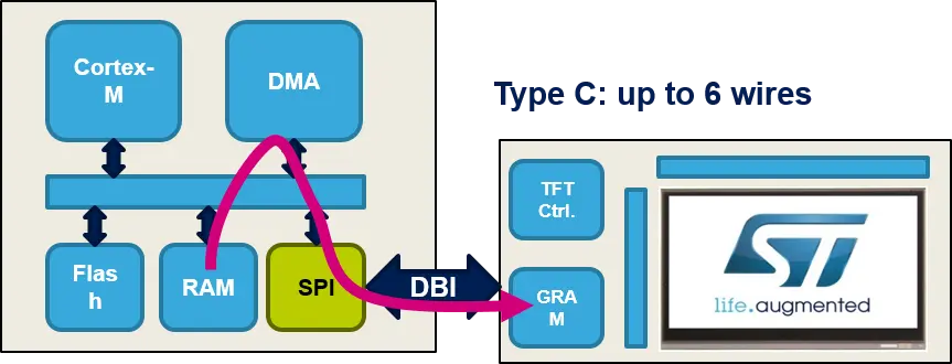
Displays with RAM
Displays with either Motorla 6800, Intel 8080, SPI, or MIPI-DSI interfaces usually embed RAM (GRAM), which has the size of 1 full framebuffer. These types of displays can connect to the MCU via SPI, FMC or DSI-host(LTDC). A second RAM (framebuffer) is required externally to the display RAM and this can be in the MCU or in external RAM.

MIPI-DSI display
In some cases the need of external RAM (external to the MCU) for storing the framebuffer is not needed, and thereby the available internal RAM in the MCU is used. If the MCU RAM is lower than 1 full framebuffer size, using the TouchGFX partial framebuffer feature is an option, allowing a very small framebuffer footprint.
Further reading
SPI display
Non-square pixels / Pixel aspect ratio
The most common pixel shape is square, but some displays use non-square pixels. Pixel ratio is the ratio between the width of a pixel and the height of a pixel. The aspect ratio using a square pixel with 100 pixel width and 100 pixel height is therefore 1/1. But non-square pixels result in a different pixel aspect ratio. If a graphics designer does not take this into account, the displayed bitmaps may be stretched like the example below.
Stretched bitmaps
Cover lense
As the display is the face of your embedded graphical user interface product, adding a cover lens could improve the look and feel. The cover lense can improve the design, scratch resistance, impact strength, colors, etc.