NeoChrom/NeoChromVG上的TouchGFX
This section discusses how to use TouchGFX on hardware having the NeoChrom GPU graphics accelerator. 本圖形加速器可大幅提升紋理映射、影像縮放和旋轉等操作效能。 這表示可建立更多進階UI,同時維持高畫面播放速率。
The NeoChrom graphics accelerator is currently available in STM32U5x7, STM32U5x9, STM32H7R7/S7 and STM32N6 microcontrollers. 開發板 適合所有產品系列。
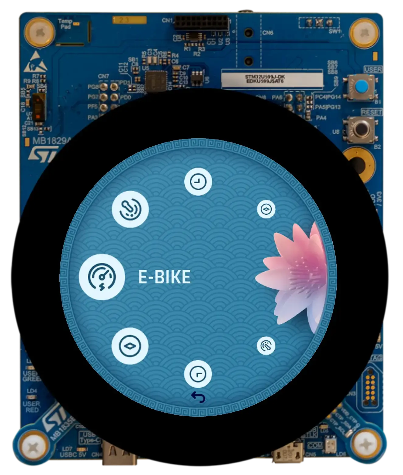
STM32U5A9探索開發板
The NeoChrom accelerator is known by the name GPU2D in source code and in STM32CubeMX.
NeoChrom及NeoChromVG
NeoChrom加速器已導入STM32U5G9進行更新,提供各項額外功能。 強化後的加速器名為NeoChromVG。 加速器包含各項延伸功能,可允許使用硬體加速向量圖形。
| 微控制器 | 加速器 |
|---|---|
| STM32U599/A9 | NeoChrom |
| STM32U5F7/G7 | NeoChromVG |
| STM32U5F9/G9 | NeoChromVG |
| STM32H7R7/S7 | NeoChrom |
| STM32N6 | NeoChrom |
NeoChrom圖形功能
NeoChrom加速器可執行基本區塊傳輸(繪圖)、混合、縮放、旋轉和紋理映射。 在含有NeoChrom的微控制器上執行時,TouchGFX會自動使用所有前述操作。
Read more about the specific functionalities of NeoChrom here.
向量圖形
新款NeoChromVG加速器可加速向量圖形。 此功能是在以TouchGFX渲染SVG圖像時使用。 GPU2D圖形加速器需要使用名為模板緩衝區的額外緩衝區。 此緩衝區與影像緩衝區的尺寸相同,不過每像素只有1個位元組。
例如,若您的影像緩衝區為480 x 480 (24bpp),模板緩衝區就必須為480 * 480 = 230,400位元組。 請務必將模板緩衝區分配至快速SRAM以獲得最佳效能。
模板緩衝區是由TouchGFX Generator負責分配。 請參閱此份指南。
利用NeoChrom縮短渲染時間。
以下範例說明NeoChrom對DMA2D及軟體渲染提供的加速效果。 我們使用Designer建立了兩個專案。 第一個專案顯示在Box背景上的Image, 第二個專案則是顯示在Box背景上的紋理映射器小工具。 小工具會在每個畫面重繪。 在以上兩個範例中,點陣圖大小為128x128、採用ARGB8888格式,並儲存於內部Flash。 影像緩衝區為RGB565格式。
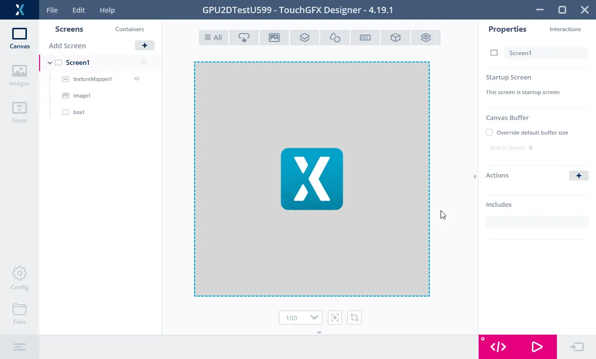
圖像專案
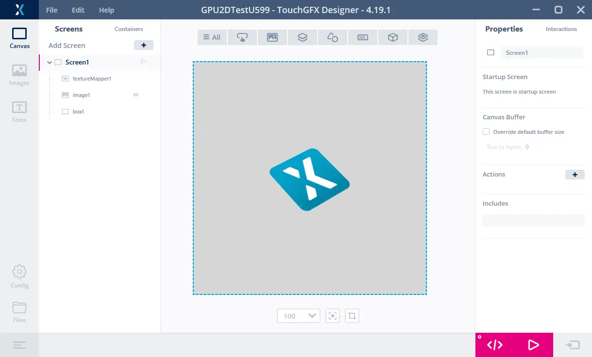
紋理映射器專案
以上兩個專案都是在STM32F746及STM32U5A9探索開發板執行。
我們將GPIO連接至邏輯分析儀以測量渲染時間:

STM32F746執行圖像專案
上圖顯示在STM32F746執行時的畫面播放速率及渲染時間。 通道00顯示VSYNC訊號。 我們可以發現顯示器以16.9 ms(A1至A2)的畫面間隔時間運作,相當於畫面播放速率59.2 Hz。 通道01顯示渲染時間(渲染時偏高,B1至B2)。 圖像渲染的時間為1.3 ms。 圖像在STM32F746的渲染速度相當快。

STM32F746執行紋理映射器專案
上圖是在STM32F746執行的紋理映射器專案。 紋理映射器的渲染時間為4.5 ms。 紋理映射器小工具的速度比Image慢很多。

STM32U5A9執行圖像專案
以下是執行圖像專案的STM32U5A9探索套件。 STM32U5A9探索套件顯示器的顯示器畫面間隔時間為12.26 ms,相當於畫面播放速率81.6 Hz。 圖像的渲染時間為0.7 ms。 我們可以發現圖像小工具比在STM32F746套件的速度更快。

STM32U5A9執行紋理映射器專案
紋理映射器的渲染時間為1.7 ms。 紋理映射器在STM32U5A9的速度也比在STM32F746更快。
渲染時間摘要
下表顯示渲染時間:
| 元素 | STM32F746 | STM32U5A9 | 增速 |
|---|---|---|---|
| 頻率 | 200 MHz | 160 MHz | 0.8 |
| 圖像 | 1.3 ms | 0.7 ms | ~2倍 |
| 紋理映射器 | 4.5 ms | 1.7 ms | ~3倍 |
我們可以發現即使減少時脈頻率,STM32U5A9仍然大幅超越STM32F746,特別是在執行紋理映射器的時候。
以上結果是以內部Flash圖像及STM32F746外部SDRAM的影像緩衝區測量所得。 影像緩衝區位於STM32U5A9的內部SRAM之中(因為一般情境就是如此)。 將圖像移往外部Flash會對STM32F746造成不良影響,因為其中使用QSPI快閃記憶體(4位元匯流排),而STM32U5A9使用的是更快的OSPI快閃記憶體(8位元匯流排)。
STM32F746探索套件執行時可使用內部RAM的480x272 RGB565影像緩衝區。 這樣可以提升效能(圖像降低為1.03 ms),但這並不是STM32F746的標準設定,因為其中使用非常大部分的內部SRAM作為影像緩衝區,只留下很少的RAM用於其他應用程式元件。 以單一影像緩衝區執行也不適用於所有的應用程式。
更豐富的使用者介面
渲染效能獲得提升後,可用於建立具有更多進階動畫的使用者介面, 例如,更多縮放或旋轉的元素。 STM32F746的顯示刷新時間為16.8 ms。 這代表應用程式必須讓渲染時間低於前述時間,以便將畫面播放速率維持在60 fps。 因此我們在這樣的複雜度情況下(16.8ms/4.48 ms),畫面上最多可有3.75個紋理映射器,或是尺寸247 x 247的單一大型紋理映射器(像素數相同,渲染時間大致相同)。 如果我們假設畫面刷新率相同,但使用STM32U5A9 CPU,就可以有14.36個紋理映射器(16.8 ms/1.17 ms),或是尺寸485 x 485的單一紋理映射器。
下圖顯示分別在STM32F746及STM32U5A9執行的兩個應用程式。 其中的概念是製作類似浮動切換的選單,元素會在移往中間時放大,並於遠離時縮小(我們在此僅對所有元素使用相同紋理)。
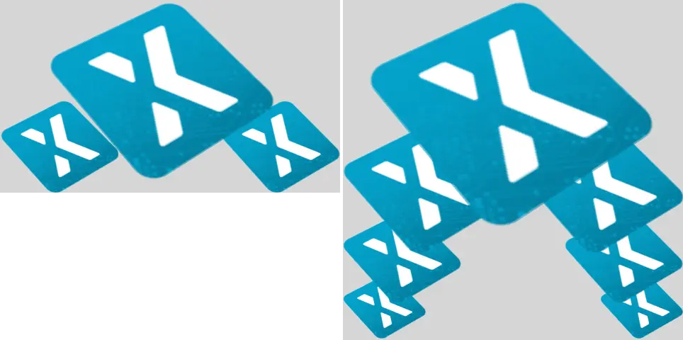
STM32F746(左側)具有480x272像素顯示,而STM32U5A9(右側)則是在480x480顯示執行以紋理映射器為基礎的浮動切換專案。
STM32F746能夠顯示三個圖示,一個是放大1.9倍的大圖示,以及兩個小圖示。 STM32U5A9能夠顯示7個圖示。 最大的圖示可放大2.7倍。
具有3個圖示的應用程式在STM32F746的渲染時間為14.38 ms。 具有7個圖示的應用程式在STM32U5A9的渲染時間為14.93 ms。 這兩項UI都能以60 fps執行,而STM32U5A9可用較高解析度顯示更多內容。
加速向量圖形
新款NeoChromVG加速器能夠加速向量圖形。 這可以開創可能性,實現各種全新類別應用程式;其中是由向量圖形扮演核心角色,而不是點陣圖。
範例之一就是地圖應用程式。 地圖可利用點陣圖建構,不過通常需要非常大的儲存容量,或是需要事先下載特定的地圖區段。
以下影片顯示在STM32U5G9執行的示範應用程式。 應用程式縮放、旋轉及平移以向量定義繪製的地圖(多個多邊形填充不同色彩及筆觸)。 影片是以800 x 480顯示搭配16bpp色彩全螢幕執行。
STM32U5G9顯示移動中的地圖。
SVG
NeoChrom GPU significantly improves SVG rendering performance. SVG rendering is partially accelerated with NeoChrom GPU and fully accelerated with NeoChromVG GPU. TouchGFX automatically leverages the available hardware.
The example below shows the performance improvements when using NeoChrom GPU. In the example, an SVG image of size 152x152 pixels is rendering on an STM32F746 (software rendering), an STM32H7S7 and an STM32N657 (NeoChrom GPU), and an STM32U5G9 (NeoChromVG GPU).

152 x 152像素尺寸的簡易SVG繪製。
下表顯示SVG圖像的渲染時間:
| MCU | 加速器 | Render time | Hardware | Core frequency | Framebuffer strategy |
|---|---|---|---|---|---|
| STM32F746 | Chrom-ART | 4.12 ms | STM32F746G-DK | 216 MHz | Double in external SDRAM |
| STM32U5G9 | NeoChromVG | 0.97 ms | STM32U5G9J-DK2 | 160 MHz | Double in internal SRAM |
| STM32H7S8 | NeoChrom | 2.80 ms | STM32H7S78-DK | 600 MHz | Double in external PSRAM |
| STM32N657 | NeoChrom | 0.78 ms | STM32N6570-DK | 800 MHz | Double in internal SRAM |
The measurements are performed using the TBSs available in TouchGFX Designer, using their default configuration. On the STM32H7S78-DK and STM32N6570-DK the GPU is driven at half the core frequency. On the STM32U5G9J-DK2 the GPU is running at the core frequency. As a result, the table shows that the STM32N657 is rendering the SVG faster than the STM32U5G9 despite the latter having NeoChromVG GPU. This difference mainly due to GPU frequency rather than inherent GPU capability: when GPU frequency is taken into account, NeoChromVG GPU remains faster and more efficient for vector rendering compared to NeoChrom GPU — and both outperform pure software rendering.
Further reading
Read more about using SVG in TouchGFX here: SVG.
向量字型
NeoChrom及NeoChromVG也能加速繪製向量字型。 您可透過向量字型這篇文章進一步瞭解如何使用向量字型。
建立專案
CubeMX及TouchGFX Generator支援NeoChrom。 In STM32CubeMX the accelerator is known by its code name GPU2D. The GPU2D accelerator is only available to TouchGFX if GPU2D is enabled in the TouchGFX configuration in STM32CubeMX. 如果您使用TouchGFX Designer提供的TouchGFX TBS(範本專案),則前述設定已經完成。 如果您製作自己的客製專案,請務必如以下所示啟用GPU2D加速器:
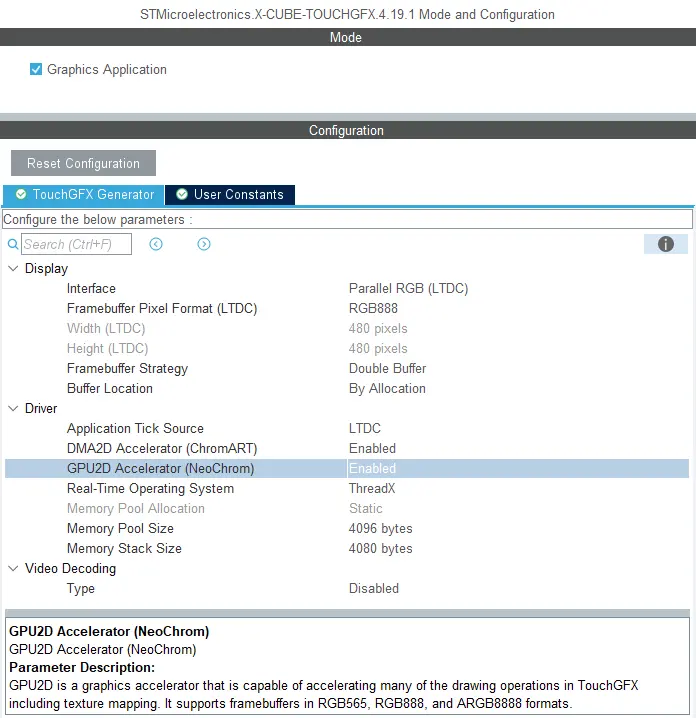
Enabling GPU2D (NeoChrom GPU) in STM32CubeMX
After enabling GPU2D press "Generate Code" in STM32CubeMX. 這樣會重新產生目標設定程式碼。 現在請於TouchGFX Designer開啟專案,並也在其中產生程式碼(F4)。
TouchGFX Designer generates assets (images, fonts, and texts) and simulator code, that matches the target configuration. 您現在已準備好編譯程式碼。
If you are starting a project from TouchGFX Designer there is no need to open STM32CubeMX unless you need to change some hardware settings.
影像緩衝區格式
The NeoChrom GPU does not natively support all color formats on all MCUs. The supported frambuffer formats can be seen in the table below:
| 微控制器 | RGB565 (16 bpp) | RGB888 (24 bpp) | ARGB8888 (32 bpp) |
|---|---|---|---|
| STM32U5x7/x9 | Natively | Natively | Natively |
| STM32H7R7/S7 | Natively | Using GFXMMU* | Natively |
| STM32N6 | Natively | Not supported* | Natively |
* These limitations are described in the following chapter.
STM32H7R7/S7 and STM32N6 limitations when using RGB888 framebuffer (24 bpp)
The internal bus to the NeoChrom GPU in STM32H7R7/S7 and STM32N657 does not support 24 bpp. At the moment there is no workaround for STM32N6, but for STM32H7R7/S7 it is possible to use the GFXMMU to achieve 24 bpp framebuffers. In this scenario, the GFXMMU is used to convert 32 bpp rendering to 24 bpp framebuffers. This means that TouchGFX runs as if it was a 32 bpp framebuffer and then the GFXMMU converts the pixel data when writing it to the 24 bpp framebuffer. To see an example of this setup, you can download the STM32H7S78_24bpp TBS from TouchGFX Designer, which uses the GFXMMU setup to enable 24 bpp framebuffer. Be aware that when using this setup it is not possible to have opaque image assets in RGB888. Instead you must select ARGB8888 as your opaque image format to utilize the full color depth of your 24 bpp framebuffer.
Step-by-step guide to enable 24 bpp framebuffers on STM32H7R7/S7
This guide provides step-by-step instructions on how to convert a project for STM32H7R7/S7 to use 24 bpp framebuffers. It assumes that the steps are implemented on an already working project with 16 bpp framebuffers. If the steps are followed on a project with 32 bpp framebuffers, step 6 can be skipped.
- Open STM32CubeMX and activate the GFXMMU for the Application context. The GFXMMU is found under the Multimedia tab.
- Enable two packing buffers and select GFXMMU_PACKING_MSB_REMOVE as the packing mode for both. One buffer is needed per framebuffer, so for a single framebuffer setup, only one buffer is needed.
Note: If you use emulated framebuffer, the first buffer is reserved for this. Therefore, you cannot use the first buffer for the 32 bpp to 24 bpp conversion if you are also using emulated framebuffer. - Set the physical addresses of the buffers enabled above. The physical address is where the 24 bpp framebuffer is placed in RAM.
- Set default alpha to 0xFF.
- Open Layer Settings in the LTDC configuration, which is also found under the Multimedia tab.
- Set Layer 0 - Pixel Format to ARGB8888.
- Set Layer 0 - Color Frame Buffer Start Address to one of the GFXMMU virtual buffers.
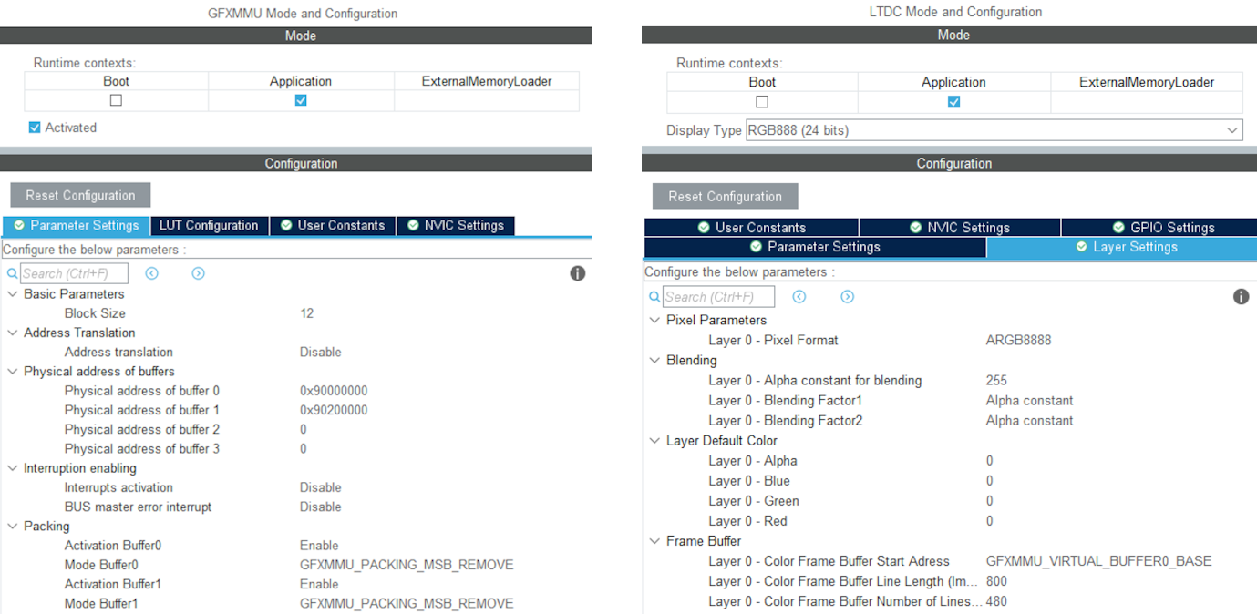
Example of GFXMMU and LTDC configuration for STM32H7S78-DK with 24 bpp framebuffers
- Open X-CUBE-TOUCHGFX, which is found under Middleware and Software Packs.
- Set Buffer Location to By Address and write GFXMMU_VIRTUAL_BUFFERx_BASE in the start addresses. Replace 'x' with the numbers of the packing buffers selected in step 2.
- Generate code in STM32CubeMX.
- Add the following code to the MX_LTDC_Init function in main.c to override the image format setting for the LTDC:
/* USER CODE BEGIN LTDC_Init 2 */
// Reconfigure pixelformat since TouchGFX project generator does not allow setting different format for LTDC and
// remaining configuration. This way TouchGFX runs 32BPP mode but the LTDC accesses the real framebuffer in 24BPP
pLayerCfg.PixelFormat = LTDC_PIXEL_FORMAT_RGB888;
if (HAL_LTDC_ConfigLayer(&hltdc, &pLayerCfg, 0) != HAL_OK)
{
  Error_Handler();
}
/* USER CODE END LTDC_Init 2 */ - Open TouchGFXHAL.cpp, which is found in the project directory under TouchGFX/target.
- Add include of HAL file for the MCU if not already present. For STM32H7R7/S7 that would be:
#include "stm32h7rsxx_hal.h" - Make the handle for the GFXMMU available by adding the line:
extern GFXMMU_HandleTypeDef hgfxmmu; - Declare a pointer to the virtual framebuffer. For example:
static uint16_t* tft = 0; - Change the implementation of TouchGFXHAL::setTFTFrameBuffer to give the true framebuffer address to the TFT LTDC controller while TouchGFX framework uses the virtual address through the GFXMMU. Assuming the packing buffers used are buffer 0 and 1, the implementation should be like this:
void TouchGFXHAL::setTFTFrameBuffer(uint16_t* address)
{
    tft = address;
    if (tft == (uint16_t*)GFXMMU_VIRTUAL_BUFFER0_BASE)
    {
        TouchGFXGeneratedHAL::setTFTFrameBuffer((uint16_t*)hgfxmmu.Init.Buffers.Buf0Address);
    }
    else
    {
        TouchGFXGeneratedHAL::setTFTFrameBuffer((uint16_t*)hgfxmmu.Init.Buffers.Buf1Address);
    }
} - Change the implementation of TouchGFXHAL::getTFTFrameBuffer() to
uint16_t* TouchGFXHAL::getTFTFrameBuffer() const
{
    return tft;
} - Open the project in TouchGFX Designer.
- Go to Config -> Default Image Configuration and select ARGB8888 as the Opaque Image Format.
- Generate code in TouchGFX Designer.
The project will now run with 24 bpp framebuffers, but TouchGFX will still render in 32 bpp. As a result, the performance will naturally be worse compared to 16 bpp and native 24 bpp. However, since native 24 bpp is not an option on STM32H7R7/S7, this is the best available solution when 24 bpp is required.
STM32U5 在外部 RAM 中具有影像緩衝區時的限制
The NeoChrom accelerator on the STM32U5 MCU family does not integrate dedicated write buffers to enable high efficiency when writing to external memories. As a consequence, the NeoChrom accelerator does a lot of "small" writes to the bus where the external memory is connected. This can lead to bus contention issues with the diplay controller which reads pixels on the same bus. Therefore, it is recommended to only have framebuffers in internal RAM when using the NeoChrom accelerator on STM32U5. If framebuffer must be in external RAM, it is recommended to not use the NeoChrom accelerator. The Chrom-ART accelerator can still be used.
Texture Cache
The STM32U5 MCU family with the NeoChrom accelerator uses a second data cache (DCACHE2) to optimize the access to texture in external RAM. This cache can also cache the internal SRAM. This is the default behavior for the second data cache.
There is generally no big benefit of caching the SRAM (it is already fast) and it is better to reserve the cache for the slower external memories (OSPI flash). Caching also requires cache maintenance operations (cache invalidation) to be performed when the CPU writes to the cached areas of SRAM.
For these reasons TouchGFX assumes that caching of SRAM is disabled for the second cache.
Since version 6.11 CubeMX generates these lines:
static void MX_DCACHE2_Init(void)
{
  hdcache2.Instance = DCACHE2;
  hdcache2.Init.ReadBurstType = DCACHE_READ_BURST_INCR;
  if (HAL_DCACHE_Init(&hdcache2) != HAL_OK)
  {
    Error_Handler();
  }
   __HAL_RCC_SYSCFG_CLK_ENABLE();
   HAL_SYSCFG_DisableSRAMCached();
}
Make sure you have the two last lines, if you do not use CubeMX.
NeoChrom的限制
The NeoChrom and NeoChromVG graphics accelerators does not support the L8 image formats (L8_RGB565, L8_RGB888, L8_ARGB8888) with TouchGFX. If you use these image formats in a TouchGFX application running on either of the micro controllers with NeoChrom/NeoChromVG the images will be drawn using DMA2D. If you use these formats with ScalableImage or TextureMapper a software fall-back will be used.
因此我們建議不要以具有NeoChrom/NeoChromVG加速器的微控制器使用L8圖像。
The NeoChrom graphics accelerator creates suboptimal anti-aliasing on graphics elements drawn with the "Non-zero fill-rule" compared to NeoChromVG. 這可能發生在將填充規則指定為「非零」的SVG檔案。 如果要避免這種情況,可以使用「奇偶」填充規則,但並不是對所有繪製都有效。