MIPI-DSI Command Mode
This section describes how to configure a MIPI DSI interface for Command Mode and how to use this configuration with TouchGFX Generator. The example used in this article will be for 16-bit RGB565 frame buffer format and generally goes through the following configurations in STM32CubeMX and code examples.
- LTDC IP
- DSI-HOST IP
- TouchGFX Generator
STM32CubeMX - Hardware configuration
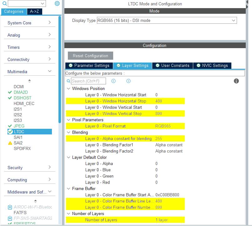
LTDC
- Mode
- Set
Display Typeto RGB565 (16 bits) - DSI Mode
- Set
- Layer Settings
- Set
Number of layersto 1 layer - Set the screen resolution in
Windows PositionandFrame Buffer Line LengthandFrame Buffer Number of Lines - Set
Layer 0 - Pixel Formatto RGB565 - Set
Layer 0 - Alpha constant for blendingto 255
- Set
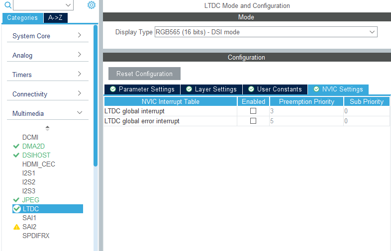
- NVIC Settings
- Both
LTDC global interruptandLTDC global error interruptare not needed, and should be disabled.
- Both
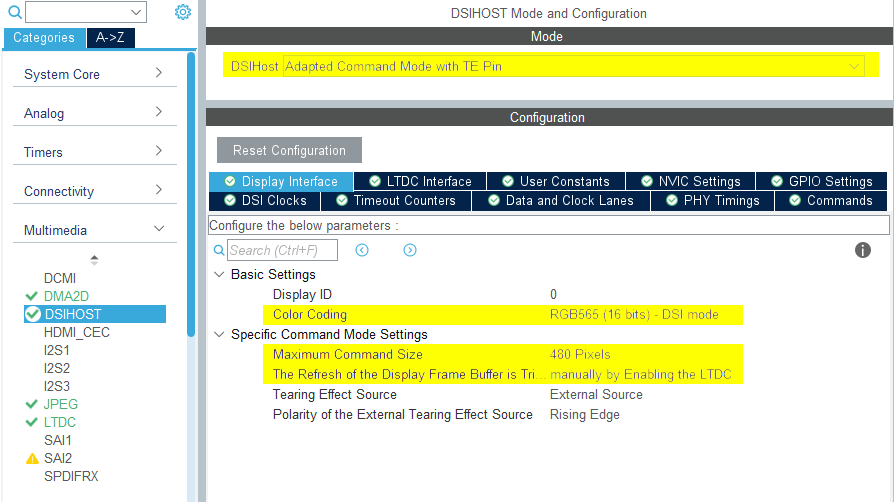
DSIHOST Configuration
- Mode
- Set
DSIHostto Adapted Command Mode with TE Pin
- Set
- Display Interface
- Set
Color Codingto RGB565 (16 bits) - DSI mode - Set
Maximum Command Sizeto a number on the order of the width of the display - Set
The Refresh of the Display Frame Buffer is Triggeredto manually by Enabling the LTDC - Remaining configurations depends on the selected LCD HW
- Set
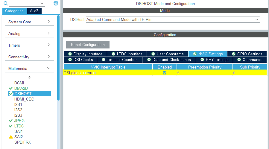
- NVIC Settings
- Enable
DSI global interrupt
- Enable
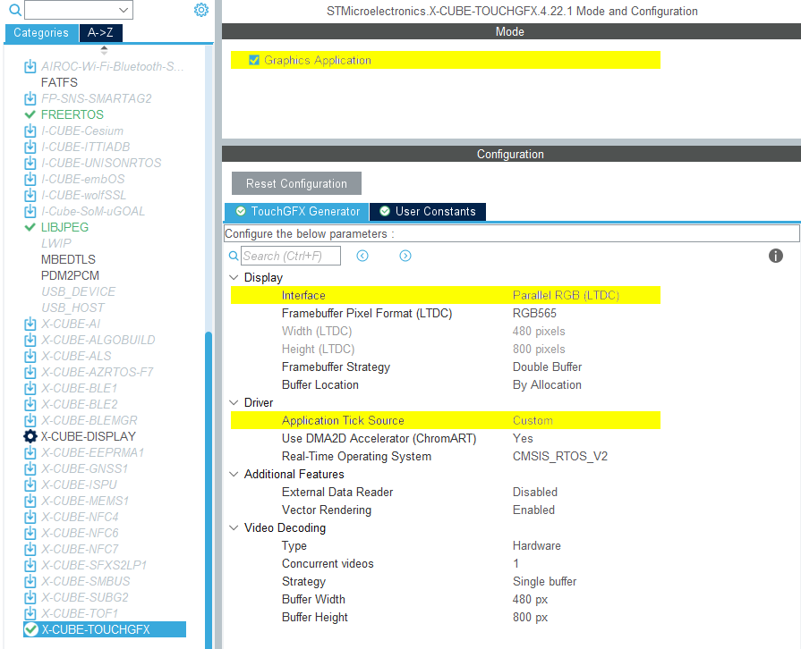
STM32CubeMX - TouchGFX Generator
- Mode
- Enable Graphics Application
- TouchGFX Generator
- Set
Display / Interfaceto Parallel RGB (LTDC) since this is still the controller the application needs to communicate with. - Set
Application Tick Sourceto Custom
- Set
DSIHOST / LTDC Initialization sequence
The call to
MX_DSIHOST_DSI_Init()must be done beforeMX_LTDC_Init(). This should be handled by CubeMX.User has to add the required initialization code specific to the used LCD controller at the end of the
MX_LTDC_Init()function, which will generally be based on the DSI HAL APIsHAL_DSI_ShortWrite()andHAL_DSI_LongWrite()/**
* @brief LTDC Initialization Function
* @param None
* @retval None
*/
static void MX_LTDC_Init(void)
{
...
/* USER CODE BEGIN LTDC_Init 2 */
__HAL_LTDC_DISABLE(&hltdc);
HAL_DSI_Start(&hdsi);
// Specific LCD controller's initialization code
...
// Turn display off until first frame
HAL_DSI_ShortWrite(&hdsi, 0, DSI_DCS_SHORT_PKT_WRITE_P1, DSI_SET_DISPLAY_OFF, 0x00);
__HAL_LTDC_ENABLE(&hltdc);
/* USER CODE END LTDC_Init 2 */
...
}
Updated TouchGFXHAL class for DSI Command Mode
One way to prevent the MIPI DSI display from turning on until the first frame in the application has beem rendered is to guard the function TouchGFXHAL::endFrame to keep the display off until first frame is rendered by TouchGFX. The TouchGFXHAL::endFrame() could be updated as below, to enable the LCD and its Backlight through a HW Timer configured for PWM output.
void TouchGFXHAL::endFrame()
{
    if (!display_on)
    {
        display_on = true;
        /* Enable the LCD, Send Display on DCS command to display */
        HAL_DSI_ShortWrite(&hdsi, 0, DSI_DCS_SHORT_PKT_WRITE_P1, DSI_SET_DISPLAY_ON, 0x00);
        /* Start PWM Timer channel */
        (void)HAL_TIM_PWM_Start(&htim8, TIM_CHANNEL_2);
        /* Enable Backlight by setting Brightness to 100% */
        __HAL_TIM_SET_COMPARE(&htim8, TIM_CHANNEL_2, 2U * 100);
    }

    TouchGFXGeneratedHAL::endFrame();
}
In DSI Command mode, the internal GRAM in the display is updated by writing a window to it using LTDC. The size of the window can be set to the entire screen area:
void LCD_SetUpdateRegion()
{
    uint8_t pCols[4] = {0x00, 0x00, 0x01, 0xDF}; /*   0 -> 480 */
    uint8_t pRows[4] = {0x00, 0x00, 0x03, 0x3F}; /*   0 -> 800 */

    HAL_DSI_LongWrite(&hdsi, 0, DSI_DCS_LONG_PKT_WRITE, 4, OTM8009A_CMD_CASET, pCols);
    HAL_DSI_LongWrite(&hdsi, 0, DSI_DCS_LONG_PKT_WRITE, 4, OTM8009A_CMD_PASET, pRows);
}
The display updates the screen line by line by setting the pixels based on the pixel values in the GRAM. To avoid tearing on the screen, each pixel value in GRAM must be updated before the display draws it to the screen. It is possible to write values to GRAM while the display is being updated, as long as the update can keep up with the scan line. The display emits a Tearing Effect signal when it is safe to start updating the GRAM. Code to enable the TE signal and set it to the last line of the display might look like this for a screen with a height of 800 pixels:
/**
 * Request TE at scanline 800.
 */
void LCD_ReqTear(void)
{
    static uint8_t ScanLineParams[2];

    uint16_t scanline = 800;
    ScanLineParams[0] = scanline >> 8;
    ScanLineParams[1] = scanline & 0x00FF;

    HAL_DSI_LongWrite(&hdsi, LCD_OTM8009A_ID, DSI_DCS_LONG_PKT_WRITE, 2, 0x44, ScanLineParams);
    // set_tear_on
    HAL_DSI_ShortWrite(&hdsi, LCD_OTM8009A_ID, DSI_DCS_SHORT_PKT_WRITE_P1, 0x35, 0x00);
}
The TE signal triggers an interrupt, which can be used to start the transfer via LTDC. Once the transfer completes, another interrupt is triggered. This example uses double frame buffers to enable drawing to one buffer while the other is transferred to GRAM.
void HAL_DSI_TearingEffectCallback(DSI_HandleTypeDef* hdsi)
{
    GPIO::set(GPIO::VSYNC_FREQ);
    HAL::getInstance()->vSync();
    OSWrappers::signalVSync();

    if (HAL::getInstance())
    {
        // Swap frame buffers immediately instead of waiting for the task to be scheduled in.
        // Note: task will also swap when it wakes up, but that operation is guarded and will not have
        // any effect if already swapped.
        HAL::getInstance()->swapFrameBuffers();
    }

    // Transfer frame buffer data
    HAL_DSI_Refresh(hdsi);
}

void HAL_DSI_EndOfRefreshCallback(DSI_HandleTypeDef* hdsi)
{
    //Point LTDC base address to the new frame buffer:
    __HAL_DSI_WRAPPER_DISABLE(hdsi);
    LTDC_LAYER(&hltdc, 0)->CFBAR = ((uint32_t)currFbBase);
    __HAL_LTDC_RELOAD_IMMEDIATE_CONFIG(&hltdc);
    __HAL_DSI_WRAPPER_ENABLE(hdsi);

    GPIO::clear(GPIO::VSYNC_FREQ);
}
