Canvas Widgets
Canvas Widget和Canvas Widget Renderer是強大的多功能TouchGFX外掛程式,在使用相對較小的存儲空間的同時維持高性能,可提供平滑、抗鋸齒效果良好的幾何圖形繪製。 但是,渲染幾何圖形必然是成本非常高的操作,如不小心使用,可能容易對微控制器的資源造成壓力。
Canvas Widget Renderer(以下簡稱CWR)是一種通用圖形API,為像素提供優化繪製,自動消除最多餘的繪製。 TouchGFX使用CWR繪製複雜的幾何圖形。 通過Canvas Widget定義幾何圖形。 TouchGFX支持許多Canvas Widget,但是就像普通小部件一樣,您可以創建自己的自訂Canvas Widget來滿足您的需求。 Canvas Widget定義要通過CWR繪製的圖形的幾何形狀,而圖形中每個像素的實際顏色則由相關Painter類定義。 同樣地,TouchGFX自帶許多Painter,但是您可以創建自己的自訂Painter來滿足您的需求。
使用Canvas小工具
TouchGFX中其他小部件的大小是自動設置的。 例如,點陣圖小部件將自動獲取包含的點陣圖的寬度和高度。 因此,對點陣圖小工具使用setXY()就足以將點陣圖放到顯示器上。
Canvas Widget沒有默認大小,其值既可以自動確定,也可以一開始就設置。 不僅要注意位置,還要正確地確定小部件的大小,否則Canvas Widget的寬度和高度將為零,並且不會在顯示器上繪製任何內容。
因此,不使用setXY(),而是用setPosition()來放置Canvas Widget並確定其大小。 另請參見下文Custom Canvas Widget部分關於如何創建和使用Custom Canvas Widget的範例。
在設置了Canvas Widget的位置和大小後,可以在其內部繪製幾何圖形。 坐標系統將使 (0, 0) 位於小部件(不是顯示器)的左上角,X軸向右延伸且Y軸向下延伸。
TouchGFX Designer中也支援Canvas Widget,可簡化使用,可自動計算記憶體需求和自動分配記憶體。
TouchGFX Designer之中可用的Canvas小工具:
通過TouchGFX Designer使用這些小部件時,可通過顯示小部件在執行時間的狀態,並簡化放置和大小調整。
存儲空間分配和使用
為了生成反鋸齒效果良好的複雜幾何圖形,需要額外的存儲空間。 為此,CWR必須具有專門分配的記憶體緩衝區,以便在渲染過程中使用。 CWR與TouchGFX的其餘部分一樣,沒有動態記憶體空間分配。
TouchGFX Designer中的記憶體空間分配
在向螢幕的畫布添加小部件時,會自動生成記憶體緩衝區。 緩衝區大小基於螢幕寬度,計算公式為 (寬度 × 3) × 5。 但是,這並非是所有情況下的理想緩衝區大小。 因此,可以重寫緩衝區大小,如下圖所示。
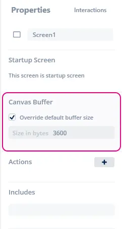
在螢幕屬性中重寫畫布緩衝區大小
Note
使用者程式碼中的記憶體空間分配
If you don't use the TouchGFX Designer to allocate a memory buffer for screens that uses Canvas Widgets, you must manually setup a buffer. It is recommended to do this in the Screen::setupScreen method.
請以私人成員的身分將此新增至螢幕類別定義:
private:
  static const uint16_t CANVAS_BUFFER_SIZE = 3600;
  static uint8_t canvasBuffer[CANVAS_BUFFER_SIZE]
然後在ScreenView.cpp的setupScreen()方法中,可新增下列程式行用於設定緩衝區。
void ScreenView::setupScreen()
{
    ...
    CanvasWidgetRenderer::setupBuffer(canvasBuffer, CANVAS_BUFFER_SIZE);
    ...
}
And in the destrcutor ~ScreenView() of ScreenView.hpp the following line resetting the buffer can be added.
virtual ~ScreenView()
{
    touchgfx::CanvasWidgetRenderer::resetBuffer();
}
需要的CWR存儲空間的量取決於要在應用中繪製的最大圖形大小。 但是,您可以保留比最複雜形狀所需記憶體空間更少的記憶體。 To handle this situation, the CWR splits the drawing of shapes into smaller framebuffer parts resulting in slightly longer rendering time, as shapes in these cases will sometimes have to be rendered more than once. 在模擬器模式下運行時,可以更細微地調查存儲空間消耗並進行微調。 只需向main.cpp中添加以下函數:
CanvasWidgetRenderer::setWriteMemoryUsageReport(true);
現在,無論繪製操作何時結束,CWR都將報告(在控制台上列印)所需存儲空間的量。 對於canvas_widget_example,可以是“CWR requires 3604 bytes”(第一個繪製操作),然後是“CWR requires 7932 bytes(4328 bytes missing)”(第二個繪製操作)。 儘管顯示CWR沒有足夠存儲空間(本例中為4328個位元組缺失),應用程式仍正常運行。 這是因為CWR檢測到可用於完成一次複雜繪製操作的存儲空間太少。 為此,它將繪製操作分割成兩項獨立的繪製操作,可以很好地繪製圖形,但需要更多時間渲染。
因此,設置正確的記憶體緩衝區大小是在存儲空間與性能(渲染時間)之間取得平衡。 好的起始值通常約為3000,但使用上述技巧通常可以找到更優的值。 如果形狀過於複雜,且分配的記憶體緩衝區太小,則部分形狀將不會繪製(將省略部分垂直像素線條),有可能完全不會繪製任何內容。 在任何情況下,渲染時間都會增加許多。
這意味著如果您希望以最快速度渲染CWR繪圖,您需要請求分配全部的記憶體空間。 But if you can go with a slower rendering time it is perfectly okay to reduce the memory buffer.
CWR坐標系統
TouchGFX中的坐標系統通常用於定址像素,以便在顯示器上定位點陣圖。 點陣圖、文字和其他圖形元素都位於坐標系統中,其中 (0,0) 是左上角像素,X軸向右延伸,Y軸向下延伸。 在CWR中,能夠使用整數定址像素是不夠的,儘管在某些特殊情況下可能足夠,但在一般情況下遠遠不夠。 為了演示這一點,假設有一個線寬為1的圓,必須被精確地嵌入一個5x5像素的方塊中。 這個圓形的中央必須位於(2.5, 2.5),且半徑必須為2 (線條由圓周兩側繪製0.5),因此中央座標需要使用分數。 類似地,如果圓應嵌入一個6x6像素的方塊,則中心必須位於 (3, 3),半徑必須是2.5,因此半徑需為小數。
這種新的圖形繪製座標定址方式意味著 (0,0) 處圖元的中心的CWR座標為 (0.5, 0.5)。 因此,包含螢幕左上角像素的方塊的輪廓如下:(0,0) -> (1,0) -> (1,1) -> (0,1) -> (0,0).
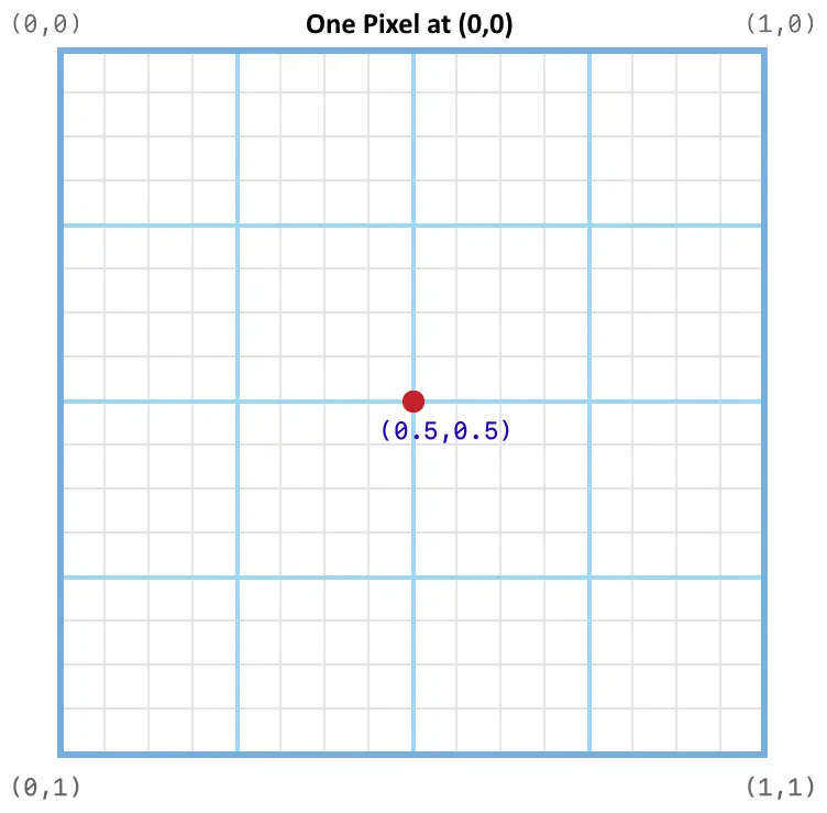
(0,0) 處像素的CWR坐標系
儘管起初看起來令人困惑,但很快會發現這是十分自然的。 點陣圖的坐標系統定址像素,Canvas Widget的同一坐標系統定址像素之前和之上的間隙。
由於圓形這種形狀通常需要移動半個像素以便讓中央置於正確位置,因此函數Circle::setPixelCenter()會將圓心置於特定像素中央,亦即比指定座標往右及往下半個像素。
Custom Canvas Widgets
實現Custom Canvas Widget需要用下列函數實現新的類:
virtual bool drawCanvasWidget(const Rect& invalidatedArea) const;
virtual Rect getMinimalRect() const;
drawCanvasWidget()必須繪製需要繪製的任何自訂小部件,並且getMinimalRect()應在包含幾何圖形的小部件中返回實際矩形。
Note
getMinimalRect() 的原因在於可以在其小部件內部到處移動幾何圖形,並且當形狀變為僅使最小可能區域無效時,改變小部件的大小和重新定位小部件通常都不切實際。 函數 getMinimalRect() 的虛擬實現可能只 返回rect;,這是小部件的大小,但這會導致被Canvas Widget覆蓋的整個區域的重新繪製,而不只是包含幾何圖形的Canvas Widget的一部分。 幾何圖形通常只佔據Canvas Widget的一小部分。
Canvas Widget全部使用Canvas類,它如上文所述壓縮Canvas Widget Renderer。 CWR有許多自動應用的優化,儘管知道幾何圖形與無效區域有關,避免無效區域之外的不必要繪製,始終是一種提升性能的好方法。
在10x10方塊內部粗略實現一個菱形方塊,結果可能像這樣:
#include <touchgfx/widgets/canvas/CanvasWidget.hpp>
#include <touchgfx/widgets/canvas/Canvas.hpp>

using namespace touchgfx;

class Diamond10x10 : public CanvasWidget
{
public:
  virtual Rect getMinimalRect() const
  {
    return Rect(0,0,10,10);
  }
  virtual bool drawCanvasWidget(const Rect& invalidatedArea) const
  {
    Canvas canvas(this, invalidatedArea);
    canvas.moveTo(5,0);
    canvas.lineTo(10,5);
    canvas.lineTo(5,10);
    canvas.lineTo(0,5);
    return canvas.render(); // Shape is automatically closed
  }
};
Note
getMinimalRect() 返回到正確矩形,否則螢幕上的圖形可能是錯誤的。為了在顯示器看見Diamond10x10,必須將繪圖器傳送至方塊以設定色彩。 請於下一節深入瞭解繪圖器的更多內容。 另外,必須正確地放置Diamond10x10並調整其大小。 結果可能像這樣:
在標頭檔中宣告
Diamond10x10 box;
PainterRGB565 myPainter; // For 16bpp displays
在程式碼之中, setupScreen()應該要有類似以下的內容:
myPainter.setColor(Color::getColorFromRGB(0xFF, 0x0, 0x0));
box.setPosition(100,100,10,10);
box.setPainter(myPainter);
add(box);
Painter
繪圖器定義一個配色方案,用於填充‘Canvas Widget’物件,因此繪圖器需要使形狀可見。 繪圖器可以為所有像素提供單一顏色(例如PainterRGB565),或者從提供的點陣圖中複製每個像素(例如PainterRGB565Bitmap)。 由於繪圖器會直接將像素寫入影像緩衝區,因此選取的繪圖器必須符合影像緩衝區或動態點陣圖的格式。 TouchGFX提供的繪圖器面向所有支援的顯示器,專門用於純色或點陣圖繪製。
繪圖器類別
下表列出TouchGFX之中可用的繪圖器。 您以TouchGFX Designer使用Canvas小工具時,Designer將會選擇正確的繪圖器,但如果您是自行編寫使用Canvas小工具的程式碼,就必須自己選擇適當的繪圖器。
| 影像緩衝區格式 | 色彩繪圖器 | 點陣圖繪圖器 |
|---|---|---|
| BW | PainterBW | PainterBWBitmap |
| GRAY2 | PainterGRAY2 | PainterGRAY2Bitmap |
| GRAY4 | PainterGRAY4 | PainterGRAY4Bitmap |
| ABGR2222 | PainterABGR2222 | PainterABGR2222Bitmap |
| ARGB2222 | PainterARGB2222 | PainterARGB2222Bitmap |
| BGRA2222 | PainterBGRA2222 | PainterBGRA2222Bitmap |
| RGBA2222 | PainterRGBA2222 | PainterRGBA2222Bitmap |
| RGB565 | PainterRGB565 | PainterRGB565Bitmap、PainterRGB565L8Bitmap |
| RGB888 | PainterRGB888 | PainterRGB888Bitmap、PainterRGB888L8Bitmap |
| ARGB8888 | PainterARGB8888 | PainterARGB8888Bitmap、PainterARGB8888L8Bitmap |
| XRGB8888 | PainterXRGB8888 | PainterXRGB8888Bitmap、PainterXRGB8888L8Bitmap |
點陣圖繪圖器支援各種點陣圖格式:
| 繪圖器 | 支援的點陣圖格式 |
|---|---|
| PainterBWBitmap | BW、BW_RLE |
| PainterGRAY2Bitmap | GRAY2 |
| PainterGRAY4Bitmap | GRAY4 |
| PainterABGR2222Bitmap | ABGR2222 |
| PainterARGB2222Bitmap | ARGB2222 |
| PainterBGRA2222Bitmap | BGRA2222 |
| PainterRGBA2222Bitmap | RGBA2222 |
| PainterRGB565Bitmap | RGB565、ARGB8888 |
| PainterRGB565L8Bitmap | L8_RGB565、L8_RGB888、L8_ARGB8888 |
| PainterRGB888Bitmap | RGB888、ARGB8888 |
| PainterRGB888L8Bitmap | L8_RGB565、L8_RGB888、L8_ARGB8888 |
| PainterARGB8888Bitmap | RGB565、RGB888、ARGB8888 |
| PainterARGB8888L8Bitmap | L8_RGB565、L8_RGB888、L8_ARGB8888 |
| PainterXRGB8888Bitmap | RGB565 (無透明度)、RGB888、ARGB8888 |
| PainterXRGB8888L8Bitmap | L8_RGB565、L8_RGB888、L8_ARGB8888 |
格狀點陣圖
由點陣圖繪製像素的繪圖器,會將點陣圖置於Canvas小工具的左上角。 形狀像素若位在點陣圖尺寸之外就不會繪製。
點陣圖繪圖器可加以設定,透過重複小工具(格狀)的方式覆蓋整個形狀。
若要啟用格狀,請在繪圖器呼叫setTiled(bool)方法:
    PainterRGB888Bitmap bitmapPainter;
    ...
    bitmapPainter.setBitmap(touchgfx::Bitmap(BITMAP_BLUE_LOGO_TOUCHGFX_LOGO_ID));
    bitmapPainter.setTiled(true);
Designer之中無法啟用格狀。
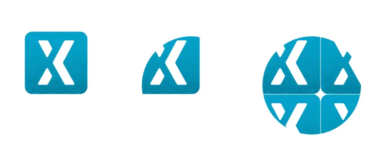
應用程式利用點陣圖繪圖器顯示圖像及圓形,並以格狀點陣圖繪圖器顯示圓形。
客製繪圖器
雖然TouchGFX提供一組預先定義的繪圖器類別,涵蓋大部分的使用案例情境,但您還是可以實作客製繪圖器。
本節將提供幾項範例作為參考,協助您激發靈感。 範例僅適用於16bpp RGB565。 如果要用於其他影像緩衝區格式,就必須進行些微修改。
客製繪圖器只是AbstractPainter類別的子類別。 適用於16bpp (RGB565)影像緩衝區的繪圖器,可使用AbstractPainterRGB565類別作為超級類別。 適用於24bpp (RGB888)影像緩衝區的繪圖器,可使用AbstractPainterRGB888作為超級類別。
這些超級類別屬於抽象類別。 客製繪圖器類別必須實作以下方法:
virtual void paint(uint8_t* destination, int16_t offset, int16_t widgetX, int16_t widgetY, int16_t count, uint8_t alpha) const = 0;
Destination指向影像緩衝區的開始位置(小工具的左側邊緣)。
Offset是指第一個像素的位置,要距離此開始位置多少像素。
widgetX、widgetY為第一個像素相對於小工具的座標(於影像緩衝區座標系統提供)。
Count是以指定alpha繪製的像素數量。
Canvas小工具將多次呼叫此方法,因此實作paint的速度是非常重要的, 但如果Canvas小工具並未經常更新,這項考量就沒那麼重要。
色彩繪圖器
最簡單的繪圖器只會將固定色彩寫入至影像緩衝區。 以下是其實作方式:
#include <touchgfx/widgets/canvas/AbstractPainterRGB565.hpp>
using namespace touchgfx;
class RedPainter : public AbstractPainterRGB565
{
public:
    virtual void paint(uint8_t* destination, int16_t offset, int16_t widgetX, int16_t widgetY, int16_t count, uint8_t alpha) const
    {
        uint16_t* framebuffer = reinterpret_cast<uint16_t*>(destination) + offset; // Address of first pixel to paint
        const uint16_t* const lineend = framebuffer + count; // Address of last pixel to paint
        const uint16_t redColor565 = 0xF800;  // Full red in RGB565
        do
        {
            *framebuffer = redColor565;
        } while (++framebuffer < lineend);
    }
};
請記得要建立繪圖器的執行個體,並將其指派至您的Canvas小工具。 將繪圖器類型的成員新增至您的類別:
Circle myCircle;
RedPainter myPainter;
在程式碼之中, setupScreen()應該要有類似以下的內容:
...
myCircle.setPainter(myPainter);
...
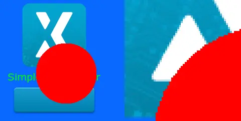
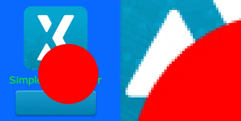
RedPainter正在繪製圓形。 右側為放大的部分。
以上的RedPainter類別會忽略Alpha參數。 這樣會讓邊緣粗糙(無Alpha混合),因為所有像素都變成完全紅色。 我們可略微更新程式碼加以改進,在需要時使用Alpha參數進行混合:
#include <touchgfx/widgets/canvas/AbstractPainterRGB565.hpp>
using namespace touchgfx;
class AlphaRedPainter : public AbstractPainterRGB565
{
public:
    virtual void paint(uint8_t* destination, int16_t offset, int16_t widgetX, int16_t widgetY, int16_t count, uint8_t alpha) const
    {
        uint16_t* framebuffer = reinterpret_cast<uint16_t*>(destination) + offset; // Address of first pixel to paint
        const uint16_t* const lineend = framebuffer + count;
        const uint16_t redColor565 = 0xF800;  // Full red in RGB565
        do
        {
            if (alpha == 0xFF)
            {
                *framebuffer = redColor565; // Write red to framebuffer
            }
            else
            {
                *framebuffer = alphaBlend(redColor565, *framebuffer, alpha); // Blend red with the framebuffer color
            }
        } while (++framebuffer < lineend);
    }
};
函數alphaBlend混合了兩個RGB565像素與提供給第一個像素的Alpha。 函數是由超級類別AbstractPainterRGB565提供。 現在此程式碼讓圓形擁有平順邊緣:
RedAlphaPainter正在繪製圓形。 右側放大的部分顯示Alpha混合。
WidgetX及WidgetY參數可用於限制繪製特定區域。 以下範例的繪圖器僅在每隔一條的水平線條進行繪製。 WidgetY用於控制:
#include <touchgfx/widgets/canvas/AbstractPainterRGB565.hpp>
using namespace touchgfx;
class StripePainter : public AbstractPainterRGB565
{
public:
    virtual void paint(uint8_t* destination, int16_t offset, int16_t widgetX, int16_t widgetY, int16_t count, uint8_t alpha) const
    {
        if ((widgetY & 2) == 0)
        {
            return; // Do not draw anything on line 0,1, 4,5, 8,9, etc.
        }
        uint16_t* framebuffer = reinterpret_cast<uint16_t*>(destination) + offset;
        const uint16_t* const lineend = framebuffer + count;
        if (alpha == 0xFF)
        {
            do
            {
                *framebuffer = 0xF800;
            } while (++framebuffer < lineend);
        }
        else
        {
            do
            {
                *framebuffer = alphaBlend(0xF800, *framebuffer, alpha);
            } while (++framebuffer < lineend);
        }
    }
};
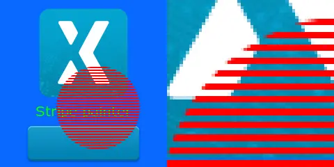
StripePainter正在繪製圓形。 右側為放大的部分。
變更影像緩衝區
本節的繪圖器並未將特定內容繪製到影像緩衝區,而是將影像緩衝區變為灰階。 其中的方法是由繪圖器讀取影像緩衝區之中的像素值(由小工具寫入,位於Circle背景)、擷取綠色元件、依此建立灰色(紅色、綠色及藍色的值相同),然後將其寫回影像緩衝區。
這種讀取及修改影像緩衝區的原則,可用於開發許多類似技巧。
#include <touchgfx/widgets/canvas/AbstractPainterRGB565.hpp>
#include <touchgfx/Color.hpp>
using namespace touchgfx;
class GrayscalePainter : public AbstractPainterRGB565
{
public:
    virtual void paint(uint8_t* destination, int16_t offset, int16_t widgetX, int16_t widgetY, int16_t count, uint8_t alpha) const
    {
        uint16_t* framebuffer = reinterpret_cast<uint16_t*>(destination) + offset;
        const uint16_t* const lineend = framebuffer + count;
        do
        {
            const uint8_t green = Color::getGreenFromRGB565(*framebuffer) & 0xF8; // Keep only 5 bits of the green
            const uint16_t color565 = LCD16bpp::getNativeColorFromRGB(green, green, green);
            if (alpha == 0xFF)
            {
                *framebuffer = color565;
            }
            else
            {
                *framebuffer = alphaBlend(color565, *framebuffer, alpha);
            }
        } while (++framebuffer < lineend);
    }
};
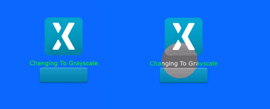
原始背景位於左側。 右側的Circle繪圖器已將圓形的內部像素變更為灰階。
位於旋轉顯示的客製容器
如果您的應用程式使用旋轉顯示,客製容器程式碼就必須將此列入考量(如果在繪圖中使用座標的話)。
以下是搭配使用旋轉顯示的StripePainter:
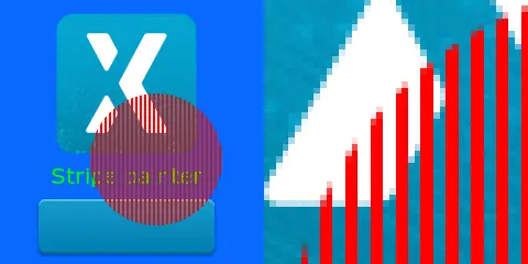
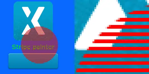
StripePainter正在繪製圓形。 右側為放大的部分。
圖像、文字及按鈕已由TouchGFX引擎旋轉,不過我們發現條紋目前與文字垂直,但其實應該是要保持平行。 線條並沒有旋轉。
問題在於影像緩衝區並未旋轉,所以繪圖器就依序在位址繪製(影像緩衝區中的像素),而線條的方向則與之前相同(未旋轉)。
如果要修正以上問題,可使用WidgetX決定要不要繪圖。 widgetX及widgetY參數於影像緩衝區座標系統中提供。 這代表如果我們在顯示中往下,widgetX就會變大,並對應至顯示座標系統之中的y。
#include <touchgfx/widgets/canvas/AbstractPainterRGB565.hpp>
#include <touchgfx/Color.hpp>
using namespace touchgfx;
class StripePainterRotate90 : public AbstractPainterRGB565
{
public:
    virtual void paint(uint8_t* destination, int16_t offset, int16_t widgetX, int16_t widgetY, int16_t count, uint8_t alpha) const
    {
        uint16_t* framebuffer = reinterpret_cast<uint16_t*>(destination) + offset;
        const uint16_t* const lineend = framebuffer + count;
        if (alpha == 0xFF)
        {
            do
            {
                if (widgetX++ & 2)
                {
                    *framebuffer = 0xF800;
                }
            } while (++framebuffer < lineend);
        }
        else
        {
            do
            {
                if (widgetX++ & 2)
                {
                    *framebuffer = alphaBlend(0xF800, *framebuffer, alpha);
                }
            } while (++framebuffer < lineend);
        }
    }
};
現在條紋的方向正確:
StripePainterRotate90正在繪製圓形。
Filling Rule
On the Shape widget it is possible to select between two filling rules: Fill-Non-Zero or Fill-Even-Odd. The Fill-Non-Zero rule is the default rule. The two figures below illustrate the difference between the two fill rules:
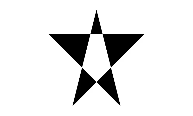
Painting a start Shape using the Fill-Even-Odd rule
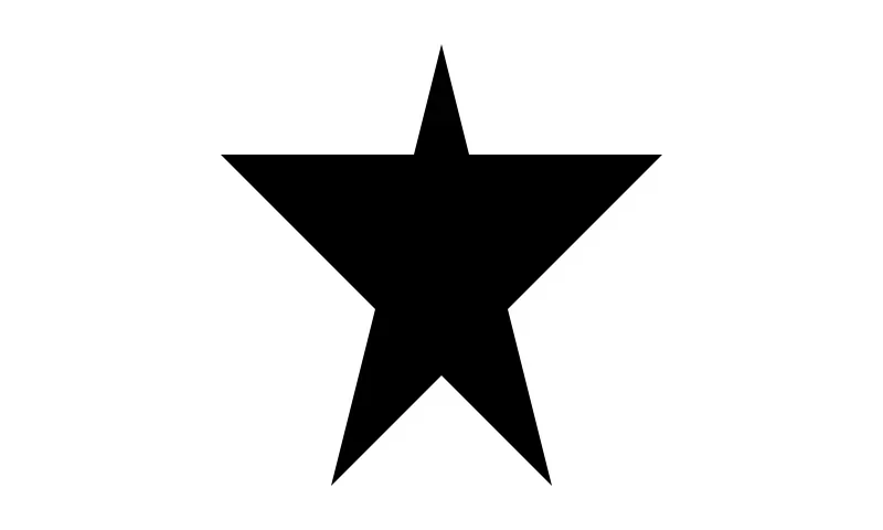
Painting a start Shape using the Fill-Non-Zero rule
The Even-Odd rule does not paint pixels that you can reach from the outside by crossing an even number (here zero or two) of edges.
The Non-Zero rule counts the number of edges going left-to-right on the path to a pixel and subtracting the number of edges going right-to-left. If the count is non-zero the pixel is painted.
The fill rule can easily be set in code:
    touchgfx::Shape<5> shape1;
    ....
    shape1.setFillingRule(Rasterizer::FILL_EVEN_ODD);